D.F. loop for 75
Transmitter hunting on the 4 Mc band.
In many sections of the country transmitter hunts are regularly-scheduled events during the summer months. Why not build this simple loop for 75 and get in on the fun?
Most readers of QST are familiar with the tremendous interest and keen competition in hidden-transmitter hunts in various sections of the country. Success in these hunts depends to a large degree upon the equipment used, particularly the effectiveness of the directional loop employed. The 75-meter loop shown in the accompanying sketches is relatively simple and inexpensive to make and has proved to be highly effective.
The loop circuit is shown in Fig. 1. The loop is tuned by capacitor Ci and the output is fed through a length of coax cable to a box enclosing L1, L2, R1 and S1, and thence through coax cable to the receiver input. A coax cable is also brought from the whip antenna to the box as shown. The whip serves as a sensing antenna, and its signal is coupled into the receiver through L1 and L2.
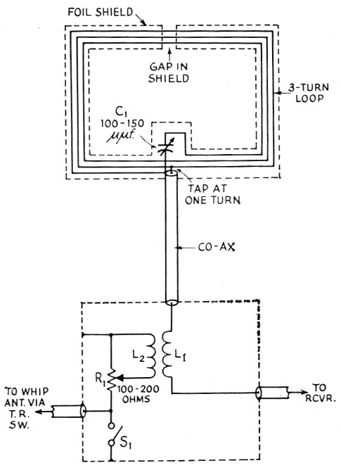
Fig. 1. Loop and sensing circuits. C1 is an air trimmer having a maximum capacitance of 100 to 150 pF. (Hammarlund APC-140 or similar, see text.) R1 is a composition (noninductive) potentiometer having a maximum resistance of 100 to 200 ohm. S1 may be of the toggle or rotary type. L1 and L2 each consist of 4 turns of hookup wire about 1 inch in diameter, the two coils being taped together. The dashed rectangle below the loop indicates a small box mounted so as to be convenient to the operating position.
The loop consists of 3 turns of approximately No. 14 wire, wound on a rectangular frame made of 1 × 2 furring strip as shown in Fig. 2. After the sides of the frame have been glued and nailed together, a table saw is used to cut 4 slots, as shown in Fig. 2B, running around all four sides of the frame. A space is routed out at the center of the bottom side of the frame as shown in Fig. 2D. This provides a means of shifting the wire from one slot to the next in winding the loop, and space for making connections. A pair of holes should be drilled for the leads to the tuning capacitor.
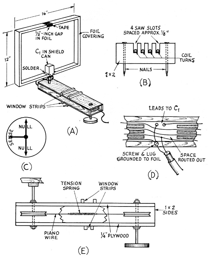
Fig. 2. Construction details of the loop.
A shows the complete loop assembly.
B shows the turns of loop wire lying in saw slots cut in the wood frame. The four sides of the loop are fastened together with nails as shown.
C is a sketch of the indicator which should be cemented to the loop-control disk.
D shows the method of making connections at the center of the bottom side of the loop. A small space is routed out to the depth of the saw slots.
E shows the mechanism used to turn the loop. The top window strips should be spaced to fit the car window frame and the lower pair to fit the glass.
The loop is shielded against capacitive pickup by wrapping the four sides with aluminum foil. The foil is a single piece 8 inches wide and long enough to extend around the perimeter of the frame. After the loop has been wound, place the frame, bottom down, at the, center of the strip and glue or cement the foil to the bottom of the frame. Then, bring the foil up along the sides and across the top, cementing the foil on as you go. Before cementing the two ends across the top of the frame, cut the foil so that there will be a gap of about ½ inch at the center.
Now, starting at the bottom, carefully wrap one side of the foil around the frame. To make a neat job, make diagonal cuts in the foil at the corners. When one side of the foil has been wrapped on all four sides of the frame, wrap the other side of the foil around the frame (in the opposite direction, of course). The seam that remains can be closed with solder. If you have some aluminum flux, you will be agreeably surprised how easily the job can be done. As an alternative, the foil can be held in place by a complete wrapping of tape around all four sides of the frame. If the soldering method is used, the ends of the foil at the gap on the top side of the loop should be held secure with tape. On the bottom side of the bottom strip of the frame, carefully cut an opening in the foil corresponding to the routed-out area.
For C1, I was able to find an old i.f. transformer that had a tuning capacitor of the right value and whose width was a hair greater than the width of the frame. Slits about 8% inch long were cut upward from each of the four bottom corners. Two opposing sides were then bent outward to form flanges while the other two sides were fastened to the edges of the frame with screws as shown in Fig. 2A. If you are not so lucky, a 140 pF. APC type trimmer may be mounted in almost any type of shield can you may have or be able to get. The shield can may then be mounted on a bridge of aluminum sheet spanning the bottom strip of the frame and fastened in the same manner as shown for the i.f. can. Before mounting the can, connect insulated leads to the tuning capacitor and fish them down through the holes in the frame as you place the can in position on the frame.
Fig. 2E shows one method of mounting the loop and orienting it from a control side the car. The wood box is made long enough that the loop will clear the roof of the car in all ositions. The box encloses a pulley drive system. o exact details are given since these will depend a large extent on the parts you can come by ost conveniently. The assembly is mounted by lowering a window of the car and clamping the box between the edge of the glass and the upper side of the window frame. The top pair of transverse strips should be spaced to fit the frame, while the lower pair is adjusted to make a simultaneous fit to the glass.
Adjustment
With S1 closed, set R1 at maximum resistance (arm at grounded end, shorting out L2). With the car in a clear area (possibly a field or pasture), time in a signal of known direction. Peak up Cl for maximum signal. Rotate the loop. You should get two sharp nulls 180 degrees apart. These nulls should occur with the plane of the loop at right angles to the direction from which the signal is coming. Now rotate the loop 90 degrees so that one end is pointing toward the transmitting station. Open the switch and slowly advance R1. If the signal becomes slightly stronger, reverse the direction of the loop so that the opposite end is pointing toward the transmitting station. You should now find a point on R1 where the signal drops to a minimum.
Set R1 at this point, reverse the position of the loop again to the maximum-signal point and note the position of the control dial. Cement an indicator like the one shown in Fig. 2C to the dial so that the null arrows are at right angles to the plane of the loop and the sense arrow points toward the transmitting station.
In operation, the loop is first swung with Sl open and the loop turned for maximum signal on "sense." This establishes the general direction of the transmitter. Then, with the switch closed, the loop is rotated to either of the two nulls which are very sharp. This will give you a pretty good bead on the fox. After a bit of practice, you will find that you have a distinct "edge" on the next transmitter hunt.
There are a few refinements that will be of appreciable assistance. An S meter is a very handy thing to have with this gear. Failing this, try installing a cutout switch on your a.v.c. system, and if your car receiver does not already have one, install an r.f. gain control.
A stationary ring around the indicator dial, with a mark indicating the heading of the car, will give a more accurate indication of the difference between the direction of the signal and the direction in which the car is heading.
If you are a real keen type, you might have enough enthusiasm to undertake the installation of a motor-driven loop, strapped to the roof like a luggage carrier, with a Selsyn indicator inside the car. Surplus aircraft indicators of this type are available and you may be able to steal the small amount of a.c. power required from your transistor power supply.
F.J.M. Marshall, VE4CX.