A 12 Volt 50 Watt transistor modulator
Packaged power in miniature.
Here's a two-stage surprise - the first, a hand-sized box can give out an easy 50 watts of audio; the second, that there's no crowding of components anywhere! Look at the pictures and be convinced.
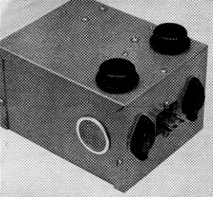
The 50 watt audio system fits into 5 × 4 × 3 inch Minibox without crowding. The driver and output transistors are mounted on the outside to facilitate cooling. The microphone jack, not visible in this picture, is on the side opposite to the one with the driver transistors and power connector.
The aim of most mobile "do-it-yourself" builders is getting the most power in the smallest package, keeping in mind cost and efficiency. With this as a goal, the author began working in late 1958 to adapt an original Delco 12 volt design(1) to a 6 volt, 25 watt modulator.
To make a long story short, the aim was accomplished but required the use of a hand-wound modulation transformer plus numerous other circuit changes. The operation of this unit proved so successful that several fellow mobile operators expressed a desire for a high power 12 volt unit. One was designed, first using hand-wound transformers, but was later modified to accommodate all-commercial components as shown in Fig. 1.
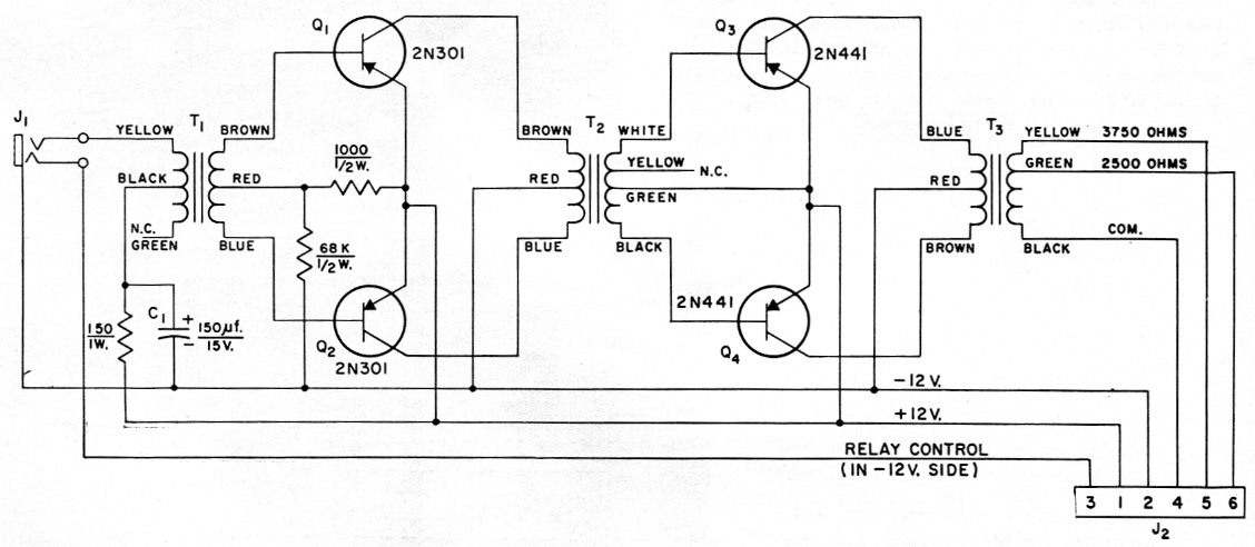
Fig. 1. 50 watt transistor modulator circuit diagram.
| C1 | 150 µF, 15 volt (Sprague TE-1163 or equivalent). |
| J1 | 3 conductor microphone jack. |
| J2 | 6 contact chassis connector, male (Cinch-Jones P-306-AB). |
| T1 | Carbon microphone to push-pull transistors (Thordarson TR-5; 150 to 490 ohm, each winding centertapped). |
| T2 | Output, 700 to 16 ohm, both windings center-tapped, 0.3 watt (Stancor TA-43). |
| T3 | Modulation, Class B transistors to Class C load, 8 ohms c.t. to 7500 or 5000 ohms, 35 watts (Stancor TA-17). |
The unit occupies approximately 61 cubic inches and is capable of over 70 watts of power output with an over-all efficiency of 60 per cent. The entire cost of the author's unit as shown eras $30.92.
The circuit uses a pair of medium-power transistors operating essentially Class B to drive a push-pull Class B output stage. In order to get the most gain and power from the driver stage, the customary emitter resistors were omitted. This resulted in some change in gain with temperature but it was not found to be objectionable. The small emitter resistor usually found in the power stage was omitted for the same reason. No tendencies toward thermal runaway were experienced in any of the eight units of similar design now in use. The bias network used in the driver stage to prevent cross-over distortion was not duplicated in the output stage because it was found to be effective only at very low levels (below 1-watt output).
As indicated in Fig. 1, neither the positive nor negative 12-volt line is grounded to the chassis. This was done so that either side could be grounded, depending on the battery polarity in the final installation.
As you have probably noticed, there is no gain control in the circuit. The over-all gain will, of course, depend on the gain of the transistors used. A suggestion would be to connect everything as shown in Fig. 1 and then if the circuit has too much gain, use the full primary of Tl rather than half of it. If the gain is still too high, a potentiometer may be substituted for the 150 ohm resistor: however, a small series resistor should be used to limit the microphone current to a safe value.
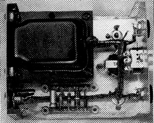
Inside view of the modulator. The microphone transformer is hidden by the input jack at the lower left; only its mounting screws are visible. The driver transformer is just below the cabling to the left of the power connector on the right-hand wall. The microphone jack is insulated from the box, as are all other components.
C1 is used to prevent self-oscillation as well as to keep ignition hash out of the input circuit. It should be at least 120 µF, and preferably 150 µF as shown.
It is not absolutely necessary, but the driver and output transistors should be matched pairs, if possible. This will allow maximum output and efficiency with the least amount of distortion.
It might also be interesting to note that,within limits, the higher the current gain of Q1 and Q2, the higher the maximum available power output before clipping or saturation occurs.
As the author has a rather low-pitched voice, special pains were taken to improve the low-frequency response. (The frequency-response curve is shown in Fig. 2.) One of the influencing factors is the amount of inductance in the primary of T3. This may be increased by removing the paper which serves as an air gap between the laminations. See Fig. 3. However, this should not be done unless the following procedure is used: With a test setup as shown in Fig. 4, apply a 1000 cycle sine-wave signal of sufficient amplitude to drive the output to a full 50 watt (353 volt r.m.s. across 2500 ohm). Now apply 500 volt d.c. as shown.(2) If the a.c. output voltage drops more than a few volts, try reinserting a thinner piece of paper between the laminations of T3. Maximum usable inductance will be obtained when the air gap is adjusted properly. In the author's unit, with no paper, the a.c. output voltage dropped 4 volt.
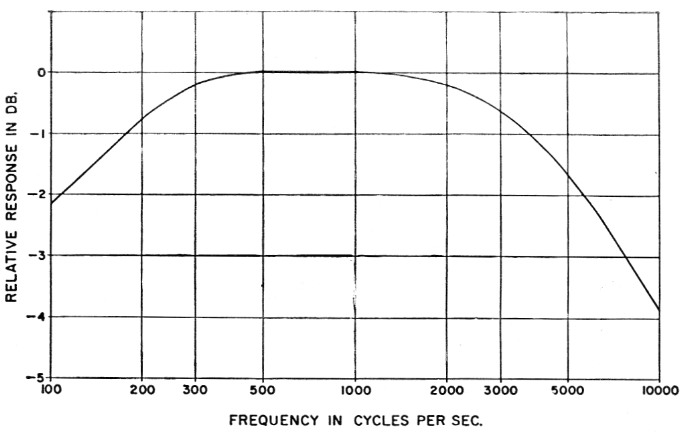
Fig. 2. Frequency-response characteristic of the modulator.
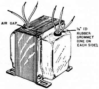
Fig. 3. Output transformer, showing air gap and modification to bring leads out the top of the case.
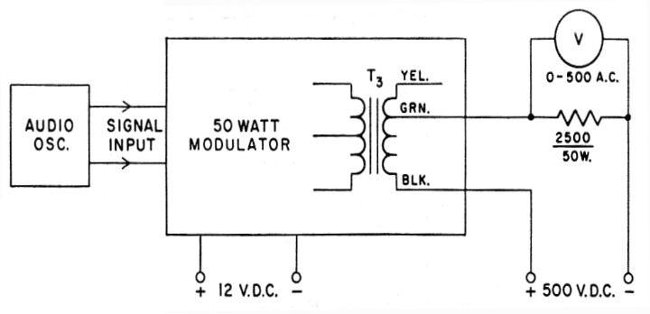
Fig. 4. Test setup for adjustment of output transformer air gap. V is a vacuum-tube voltmeter.
In order to deliver 50 watt, the output transistor must look into a 4 or 5 ohm load. The TA-17 modulation transformer has an 8 ohm primary with a 5000 or 7500 ohm secondary. Therefore, to reflect 4 ohm in the primary, the secondary must see either 2500 or 3750 ohm as a load. This transformer is rated at 35 watt by the manufacturer but should give good service at 50 watt while being used in intermittent mobile service.
Construction
The unit was constructed in a 3 × 4 × 5 inch Minibox (Bud type CU-2015A). The driver transistors are mounted on either side of the Jones plug on one end of the box while the output transistors are mounted on top near the same end. The modulation transformer is mounted on the opposite end along with the mike jack. See Fig. 3 for modification to bring leads out top of transformer. The input transformer, T1, is below the mike jack, along with the terminal strips used for mounting the small components. The driver transformer is located between the output transistors. Two 1-inch ventilating plugs (General Cement type 1708-C) were used on either side of the box to facilitate cooling.
Transistor Mounting
All four transistors must be insulated from the chassis. If the output transistors are ordered directly from Delco 3 in small quantities, the mounting kits will be included. Delco also makes a mounting kit (Part No. 7274775) which fits the driver transistors.
If a painted Minibox is used, be sure to clean off the paint under the transistors to insure good heat conductivity. Heat transfer will also be improved if a light coat of silicone grease is applied to both sides of the mica washers before mounting. In the author's unit the transistors were painted flat black, which also helped to dissipate heat.
Heat sinks
At first it was rather doubtful whether the heat sink provided by the Minibox would be adequate, but after running extensive tests, the results of which are shown in Fig. 5, it was found satisfactory. Actually, the unit was operated at 50 watts with a sine-wave input for 30 minutes with no additional increase in temperature. By calculating the thermal gradient it was found that a mounting stud temperature of at least 80 degrees C. could be reached before damaging the output transistors.
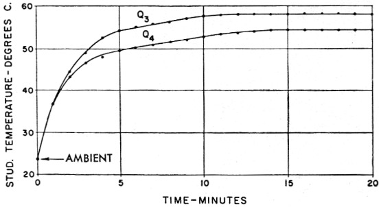
Fig. 5. Rise in stud temperature of the Class B transistors (2N441) over a 20 minute period of continuous operation at 50 watt output.
If the unit is to be operated at power levels greater than 50 watt or is to be mounted close to other components which dissipate a large amount of heat, a convection-type heat sink such as manufactured by Delco 4 or Modine 5 should be used for the output transistors. In any case, the power transistors should be placed where free air can circulate.
As to the merits of using a painted box or an aluminum one, a test was run on both. The painted box allowed the transistors to operate from 4 to 6 degrees C. cooler.
If one output transistor appears to run quite a bit hotter than the other, it sometimes helps to interchange them. This is usually caused by the fact that very few transistors have exactly the same thermal characteristics and few transformers have a perfectly balanced winding. If you happen to have the transistor with the higher thermal characteristics on the low-resistance side of the transformer winding, that transistor will run quite a bit hotter.
Testing
Test the unit by connecting a 2500 ohm 50 watt resistor between terminals 4 and 6 on J1 of Fig. 1. A vacuum-tube voltmeter and an oscilloscope should also be connected across the same terminals. With no signal the static d.c. current will be approximately 50 mA. With a microphone plugged in, it will be about 100 mA, total.
To test the unit properly, a 1000 cycle sinewave signal should be applied through J1. While watching the scope, increase the input signal until saturation or clipping begins. This will be the point of maximum output before excessive distortion. The output power can then be calculated by dividing the square of the output voltage by the load resistance. The d.c. supply current will be 7 ampere for 50 watt output.
The maximum output will not only depend on the gain of the transistors but also on the supply voltage, as indicated in Fig. 6. Most cars with 12 volt systems will supply about 14 volt with the engine running, so it should not be much trouble to obtain at least 50 watt of output.
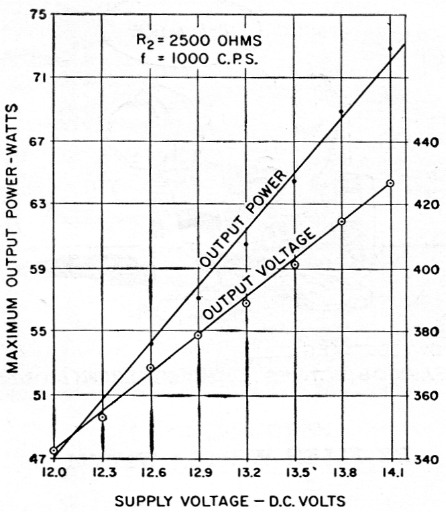
Fig. 6. Maximum power output (just below clipping level) vs. primary supply voltage. Power is calculated from the a.c. voltages on the right-hand scale. A v.t.v.m. calibrated in r.m.s. was used for measuring the output voltage.
Notes
- "Transistor application note 6-B," Delco Radio Division, General Motors Corporation, Kokomo, Indiana.
- Do not leave the d.c. voltage on for more than a few seconds because you will be dissipating 100 watt in the 50 watt load resistor.
- All standard transistors made by Delco are now available at very reasonable prices directly from Kokomo, Indiana.
- Part No. 7270606 (blank) or 7270725 (punched). Also, Insulating Spacer, Part No. 7269634.
- Model No. 1E-1155B, Modine Mfg. Co., Racine, Wisconsin.
Dave Harper, W4NIQ.