Improved selectivity for older receivers
A low-cost half-lattice crystal filter.
The author writes, "If you try this filter and do not get improved operation, you have made a mistake somewhere." Less than three dollars' worth of surplus crystals does the trick.
Gather 'round, sidebanders and a.m. men. Here is the answer to your prayers. An inexpensive (cost me $2.75) band-pass filter with continuously-variable selectivity control. Any of the older Hammarlund receivers can be so equipped without any defacing and a minimum of work. The filter can be easily built from scratch for other receivers. Several of these filters have been built and there have been equally smooth and stable results in every case. The filter has an almost perfect flat top and introduces no ringing whatsoever. The variable selectivity makes possible best results on either a.m. or s.s.b.
Crystals
Here is how it is made. Get surplus crystals with channel numbers 49, 50, 51, 52, 53 and 54. These are suitable for a 465 kc i.f. strip, such as the one in the Super Pro. For a 450 kc strip (HQ-129X), use crystals with channel numbers 41, 42, 43, 44, 45 and 46. Buy six small plastic crystal sockets and a 3-12 pF ceramic trimmer. Now to work.
Modification
Remove the crystal filter from the receiver. Take off the top and sides. Unsolder and remove the present crystal holder. Remove the mica-compression neutralizing capacitor. With wire cutters clip off the last two of the small resistors on the selectivity switch. These are the 300-and 2000-ohm resistors. Also, remove the wires to the crystal-shorting ("off") part of the switch.
Now take a look at the filter compartment and compare it with the photo of the rebuilt filter. You will notice that the crystals will not fit above the coil can at the top of the filter as shown in the photo. (The unit is inverted in the pictures.) To make room, elongate the mounting holes in the coil cans with a small file and move the coil cans down until the crystals will just fit tightly above. You will find that the remaining two crystals will fit as shown by rearranging the wires. Solder the new resistors (100 and 200 ohms) on the selectivity switch.
Now replace the top of the box. Solder in the new ceramic trimmer as shown in the photo. It is very important that the two series crystals, Y5 and Ys, be placed as shown, with the lower-frequency crystal across C2. If these two crystals are interchanged, the filter will not work!
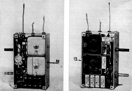
Side views of the crystal-filter unit. The left-hand view shows the phasing capacitor in the upper right-hand corner. The right-hand view shows the ceramic neutralizing capacitor at mid left. In these views, the unit is inverted in respect to its normal position in the receiver.
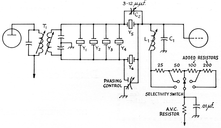
Fig. 1. Circuit of the half-lattice filter replacing the conventional crystal filter found in older-model receivers. The specific application shown is for Hammarlund Super-Pro and HQ-129-X receivers. T1 and C1 L1 should be aligned to the midfrequency of filter. Resistances are in ohms, and resistors are ½ watt.
| C1L1 | I.f. circuit following filter (filter output). | |||
| C2 | Ceramic trimmer. | |||
| T1 | I.f. transformer preceding crystal filter (filter input). | |||
| Crystals | ||||
|---|---|---|---|---|
| 465 kc I.F. | 450 kc I.F. | |||
| Freq. (kc.) Channel No. | Freq. (kc.) Channel No. | |||
| Y1 | 461.1 | 49 | 446.3 | 41 |
| Y2 | 462.9 | 50 | 448.1 | 42 |
| Y3 | 468.5 | 53 | 453.7 | 45 |
| Y4 | 470.4 | 54 | 455.5 | 46 |
| Y5 | 464.8 | 51 | 450.0 | 43 |
| Y6 | 466.7 | 52 | 451.8 | 44 |
Wire in the crystals as shown in Fig. 1. Check your wiring carefully. While the circuit is simple, the wiring may be very confusing, so double check. To finish up, cement a piece of paper on the inside of the box cover on the crystal-socket side to avoid chance shorting of the socket terminals to the metal case. Now reassemble the box and replace the filter in the receiver.
Alignment
Here is where patience and good work are necessary. Alignment must be perfect. The best way to do the job is with a BC-221 or other very stable generator, using the S meter of the receiver as an indicator. Use an unmodulated generator signal. Let the receiver and generator warm up for a couple of hours. Then roughly align the i.f. transformers following the filter to a frequency midway between the two center crystal frequencies (465.7 kc for a receiver having a 465kc i.f. or 450.9 kc for a receiver having a 450kc i.f. amplifier). If the receiver is a Super-Pro, do not forget to align very carefully the a.v.c. amplifier transformer as you go along - adjust the lower slug (mixer plate) for maximum output.
Now tune the receiver to background noise on the highest-frequency band. Set the phasing control at "two o'clock," the selectivity switch at the third position, and set the neutralizing capacitor for maximum "crystal" sound (a hollow, muffled sound). Next, switch the receiver to a low-frequency band. Set the selectivity switch at the No. 2 position (third switch position) and tune the signal generator very carefully to the receiver frequency.. You will notice two decided peaks on the S meter at the band-pass crystal frequencies. Set the signal generator exactly between these peaks and very carefully align the entire i.f. strip, starting with the bottom filter slug. Do not touch the top (first i.f. grid) slug. Repeat this process until alignment is perfect. Always recheck the generator to make sure it is exactly between peaks. Do not forget the a.v.c. amplifier transformer if the receiver is a Super-Pro.
Final adjustment
When this is finished you come to the most important adjustment of all - at the top slug on the filter can. This adjustment can best be made by ear with the receiver tuned to background noise on the highest-frequency band. Do not use the signal generator. As you turn the slug adjustment you will come to a point where the noise quickly changes from a "crystal" sound to a natural, higher-frequency sound, and then back again. Set this slug precisely on the leasthollow-sounding peak. This adjustment is the one that removes the double peaks on the flat top. If the adjustment is properly made, the S meter will show no peaks whatever when tuning across a signal. The alignment is now finished.
The phasing control is now the band-width control, with the broadest position at "9 o'clock" and sharpest at "2 o'clock." By varying the neutralizing capacitance, the maximum-selectivity position can be placed at any desired point on the phasing-control dial. Best all-around results are obtained with the selectivity switch on the No. 2 and 3 positions, although some of the s.s.b. men may like the sharper positions. The phasing control can also move the two side notches slightly inside the pass band to remove heterodynes or chatter.
If the filter is properly adjusted the improvement in selectivity will be immediately apparent. It makes a new receiver out of the old HQ-129X.
John M. Palmer, W1SGN.