Lightweight utility mast
An inexpensive one-man 35 footer.
Here is a simply-built and easily-erected mast that will put a wire antenna or lightweight beam 35 feet into the air. It requires a single set of guys.
An outstanding feature of the 35 foot mast shown in Fig. 1 is that it can be put up by one man. This is largely due to the fact that most of the weight is in the base section. The long 20-foot center section is made of 1 × 2 stock and can easily be held in one hand. True, the mast requires guying. But light-duty guying presents only easy problems - nothing like those associated with the designing, building and raising of a self-supporting mast. And the guys make the task of raising or lowering the mast much easier.
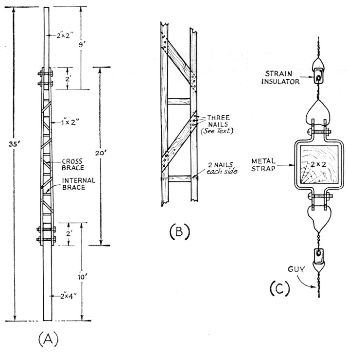
Fig. 1. Sketch of the lightweight 35-foot mast.
The detail at B shows the cross bracing.
C illustrates a clamp for attaching guy wires at the top of the mast.
This mast has rendered good service at K4URX for several years. It's handy to put up when trying a new antenna, or a new location for an old antenna. For about a year it supported a 6-meter ground plane, the radials and radiator of which all were made of 5A-inch thin-wall electrical conduit. In this service the mast was lashed to the side of the house with the top 10 feet and the antenna self-supporting. Here the mast withstood several gusty blows with winds up to 50 or 60 miles per hour. The structure is fairly flexible and gives with the wind. Fitted with wire, stand-off insulators (either commercial or home-brewed of polystyrene strips), and perhaps a whip at the top, the mast can serve for a vertical antenna. In this use it would be selfsupporting to a degree because there would be no lateral strain at the top from either the pull of a horizontal wire or the wind resistance of a beam.
Materials
Employing basic "A-frame" construction, the mast consists of a length of 2 × 4 for the base section, a latticed mid-section made of 1 × 2 wood, and a top section of 2 × 2 stock. Actual lengths shown in Fig. 1 can be varied to some extent to suit the builder's requirements. It should be borne in mind, however, that a longer base section will add to the weight and a longer top section will weaken the over-all structure.
Two types of braces spaced 12 inch center to center are used on the mid section, all made of 1 × 2 stock. As illustrated at B, the outside cross braces are set at 45 degrees, and alternate in direction and from front to back. The short inside braces fit in between the sides and are graduated in length from slightly less than the width of the 2 × 4 base to slightly more than the width of the 2 × 2 top section. The exact lengths of the cross braces and internal braces can be determined as the mast is put together.
In the model illustrated, ordinary small finishing nails were used to fasten the braces to the 1 × 2 rails. However, aluminum nails would be preferable. Brass screws probably would be best, but they are expensive and require guide holes and a considerable amount of elbow grease. Cement-coated nails probably would provide stronger construction than noncoated nails, but still would subject the mast to rust damage over a period of time.
The mid section may be fastened to the 2 × 4 base with either nails, lag screws or bolts, the latter being preferable to anticipate future construction changes. The top-section 2 × 2 should be set into the 1 × 2 arms and secured with two ¼ inch bolts. Nails here could split the wood all too easily.
Ideally, all of the wood pieces should be given a prime coat of outside white paint before assembly, and a second coat after construction is completed. However, the operator at K4URX (a lazy, shiftless type) used only one coat of white paint immediately after construction and the mast has suffered no appreciable damage in four years of exposure to the elements.
Assembly
If the lumber yard's 1 × 2 furring stock is composed principally of "knotty spruce," the chances of getting two clear 20-foot lengths are pretty slim and it would be best to have them cut from a 1 × 4 piece that is free of knots. Another point to watch in procuring these strips is their straightness. Crooked 1 × 2 rails will make a crooked mast. This also applies to the 2 × 2 top section and the 2 × 4 base.
Do not precut the braces. Instead, have a supply of 1 × 2 stock ready to use for bracing as you go along.
With all material on hand, lay the four principal pieces out to form the three sections on a surface as flat and hard as you can find. A level driveway serves excellently. Lacking this, the pieces may be laid on the ground, supported at strategic points by bricks or blocks of wood built tip so that the entire mast is level and straight.
First, tack the two rails to the base and top sections with light finishing nails to hold the pieces in place. Then measure and cut the internal braces to the various lengths necessary to taper the 1 × 2 rails gradually from the width of the 2 × 4 base down to the width of the 2 × 2 top section. The taper is so gradual that it is not necessary to bevel the ends of these short inside braces. Nail them in place, taking care to keep the entire structure as straight as possible.
Nailing on the cross braces comes next. The trick that prevents the nails from splitting the ends of the cross braces is to use over-length braces - that is, to extend the ends a couple of inches beyond the outer edges of the long 1 × 2 side rails and then saw them off flush after they all are in place. If you think this is a waste of wood, just try nailing them on after precutting and see how many ends split. Also, anyone who can precut these angled braces to fit precisely this tapering structure is a minor mathematical genius who is wasting his time with structures like this! Alternate the placing of the cross braces on the rails between the front side and the back side. Use three nails at each end of each brace, aligning the nails diagonally across the side rails to reduce the danger of splitting the rails.
While the three sections are tacked together, drill the bolt holes in their proper places through all pieces at once.
A clamp for top guys and antenna insulator or a pulley can easily be fashioned from two strips of scrap metal as shown in Fig. 1C. Other means can be devised for fastening other types of antennas to the top of the mast although, as previously mentioned, this mast is for light duty. It is possible that a very lightweight rotator and small u.h.f. antenna could be supported. However, no matter how light the rotator, the increased wind-loading surface adds danger; serious u.h.f. work usually demands stacked arrays larger than can be handled by this mast.
Installation
Base anchoring is no problem. Two points should be observed: (1) prevent the base of the mast from moving sideways, and (2) keep the end of the 2 × 4 out of surface water in wet weather. Two methods are illustrated in Fig. 2. The cinder-block mounting of A has been used successfully with the mast described here. Two cinder blocks are used with the bottom one on its side to raise the mast out of the mud, and the top block placed normally with the end of the 2 × 4 slipped into one of the holes in the cinder block. Four stakes driven into the ground around the cinder blocks prevent lateral movement of the blocks and the base of the mast. Loose construction permits good water drainage, and leaves the mast- relatively free for easy removal, even in freezing weather, although you may have some trouble getting a cinder block out of frozen ground. It is feasible, too, to set a 4 × 4 cedar post in the ground and bolt the mast to it as shown in Fig. 2B, although this imposes a degree of permanency on the location. At the time of this writing, the base section of the mast is clamped to the metal vertical member of a yard-arm clothesline support, which itself is set in concrete in the earth.
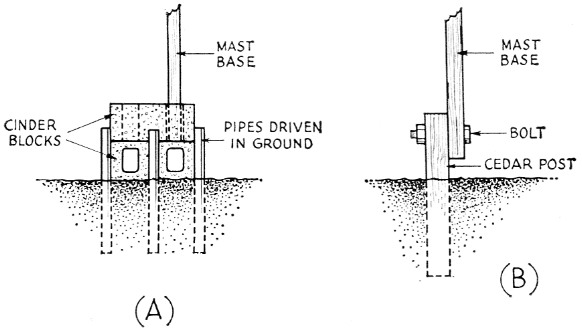
Fig. 2. Methods of anchoring the base. At A, cinder blocks help to prevent deterioration of the base. At B the base of the mast is supported by a cedar post.
Metal fence posts, sledged into the earth, make excellent guy anchors because they raise the lower ends of the guys off ground sufficiently to prevent the danger of tripping over them. Alternatively, trees, house corners, clothes poles or iron pipes can be used with confidence with a light-duty mast like this one.
Guys can be almost anything from nylon cord to conventional TV mast wire. Naturally, the heavier the better. Quarter-inch Manila rope serves well and is easy to handle, although it weathers fast. This action can be slowed by soaking the rope in the liquid-type preservative used for wooden fence-posts.(1) To reduce fraying of guy ropes, either standard thimbles or small egg insulators can be used.
Raising or lowering the mast becomes simple if at least two guys first are fastened in approximately their correct positions while the mast is still horizontal on the ground. One simply lifts the base section and pushes against the guys and - presto! - the top end of the mast soars upward as one walks toward the spot where the base will be set. See Fig. 3. However, some caution must be exercised. Don't walk too far if you have only two guys in place or the mast will soar downward in the opposite direction - and much faster, too! Set the base down on the ground before the mast reaches the perpendicular. It can be straightened and the guys tightened after the third guy or antenna wire is in place and ready to take some strain. With judicious juggling, neither a side wind nor a tail wind will interfere with this erection process, and it even takes a pretty stiff headwind to cause any trouble.
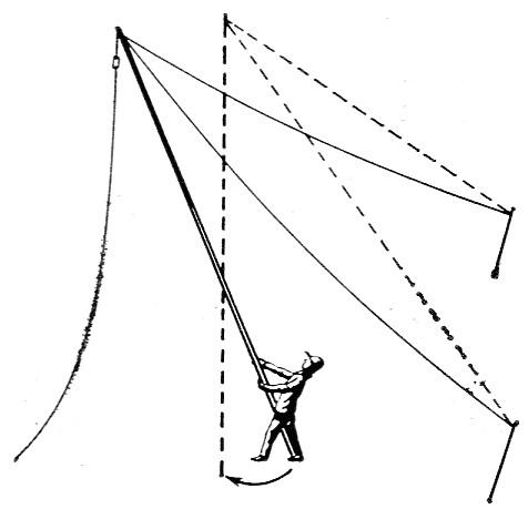
Fig. 3. Sketch showing how the most is easily raised by one man. With two guy wires attached to their anchorages, the erector "walks" the base of the mast in the direction of the third guy-wire anchoring point until the mast is nearly vertical.
Notes
S.E. McCallum, K4URX.