Experimental transceivers for 5650 Mc
Duplex phone communication with home-built gear.
Most equipment thus far used in amateur work on frequencies above 2000 Mc has leaned heavily toward the use of surplus components. Here is something a bit different: two complete stations for the 5650 Mc band that are largely home built. The "plumbing" is handmade; the bores are hardware-store funnels; the i.f. systems simple adaptations of circuits familiar to nearly everyone. These stations provide good-quality duplex phone communication over line-of-sight paths.
The 2K26 klystron, available on the surplus market, is rated at 120 milliwatts output at 6000 to 7000 Mc., but its tuning range extends well into the amateur band at 5650 to 5950 Mc. Two transceivers using this klystron are described herewith. Each station is built in two principal parts: an r.f. unit containing the klystron oscillator and crystal mixer, mounted in a wave-guide assembly with horn antenna attached; and a remote-control section consisting of the i.f. system for reception, power supplies, audio equipment, and a fine-tuning frequency control. The i.f. system can be an f.m. broadcast receiver, or it can be built for the purpose. Two examples of the latter are shown, though not described in full detail.
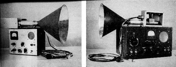
Two microwave transceivers by W8DRR. The r.f. units are identical, but different control and modulator sections are used. The station at the left utilizes a superregenerative detector for simplicity. The other employs an f.m. receiver built from readily available TV components. The horn antennas, suitable for short-range communication, are made from hardware-store funnels.
Each station transmits and receives simultaneously, in the manner commonly used in amateur microwave work. The klystron serves as the transmitting oscillator and as the receiver local oscillator, simplifying the equipment needed for two-way communication. The oscillator radiates energy into space via the horn antenna. At the same time a small amount of energy is injected into the crystal mixer in the assembly. The same thing is happening at the other end of the path, permitting duplex communication on voice with a single antenna and klystron at each end, so long as the antennas are aimed at each other and the two oscillators are separated in frequency by the amount used for the intermediate frequency in the receiver.
The klystron oscillator is readily frequency-modulated by varying its repeller voltage, so f.m. detection is the logical solution to the receiver problem. In one of the units the f.m. detector is a simple superregenerative receiver. The other uses a conventional f.m. limiter and discriminator. If some form of automatic frequency control is used, only one of the stations need be tuned to set the system up for communication, and to keep it in tune once the other signal is located.
A three-conductor shielded cable and a section of coax of equal length connect the r.f. and control sections of each station. This permits mounting the r.f. unit in an elevated or otherwise favorable position. Line loss is not a serious factor, as the coax carries only the intermediate-frequency energy. The units described are not waterproofed, as they were intended for indoor use, with the horn antennas shooting through windows.
Electrical Details
The 2K26 kylstron requires 6.3 volt at 0.44 amp. for the heater; +100 to +300 volt at 25 mA from a regulated and well-filtered supply for the cavity; -90 to -120 volt, also regulated and well-filtered, for the repeller. The repeller requires only a few microamperes, so this supply presents no problem. The crystal detector is wired so that the d.c. component of the rectified injection signal and the i.f. signal are transmitted through the coaxial cable to the control unit.
Here they are separated, the crystal current going to the metering circuit and the i.f. signal to the f.m. i.f. input. The crystal current provides a convenient means of indicating oscillation.
While the two r.f. units are identical, the control units are not. The first one built contains a +125 volt 50 mA power supply for the receiver. An 0B2 regulator provides +108 volts for the klystron cavity. The same power transformer feeds a selenium rectifier to obtain -125 volts. Another 0B2 provides -108 volts for the repeller circuit. The i.f. system has a grounded-grid amplifier, a superregenerative detector (using slope detection for f.m.) and two stages of audio, with speaker and headphone output. A single 6AT6 serves as speech amplifier and modulator, providing more than enough gain for a crystal microphone. A control is provided for electrical adjustment of the klystron frequency.
The second unit is more elaborate, with supplies for +240 and -108 volts, a Mallory continuous tuner (54-190 Mc), two stages of 23 Mc i.f., a limiter, discriminator and two stages of audio with speaker and headphone output. A zero-center microammeter reads crystal current, and limiter and discriminator voltages. A 6AU6 speech amplifier drives a 6AT6 modulator. Electrical and automatic frequency control are incorporated in this unit. A 6C4 in a simple circuit does a good job in maintaining a constant intermediate frequency even though both klystrons might otherwise be shifting frequency constantly with line voltage or temperature changes.
Anyone interested in duplicating these transceivers can simplify the job by using a separate f.m. receiver for the i.f. system. The only requirement is that the receivers at both ends be capable of tuning to the same frequency, such as 88 Mc. If you build your own i.f. it can be on any frequency above about 30 Mc or so.
A simple control unit for use with a separate receiver would require a positive power supply of 270 volt at 60 mA, with regulated output of 258 volt, a negative power supply giving 125 volt at 50 mA, with regulated output of 108 volt, a 6AT6 cathode-follower modulator, a 6C4 a.f.c. tube, a zero-center 50 µA meter and single-pole 3-position switch, B+ and a.f.c. switches, frequency and microphone-gain controls, and suitable power and coaxial fittings for connection to r.f. section and separate receiver. Such a setup is shown in Fig. 1.
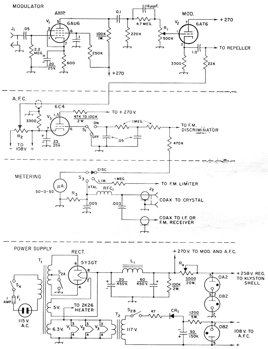
Fig. 1. Schematic diagram and parts information for the power supply and control unit of the W8DRR microwave transceivers. Unless otherwise specified, capacitor values are in µf. Capacitors marked with polarity are electrolytic. Resistors ½ watt unless specified.
| CR1 | 65 mA selenium rectifier. |
| F1 | 1 A fuse and holder. |
| J1 | Shielded microphone jack. |
| J2 | Coaxial chassis fitting. |
| L1 | 10 H 110 mA choke (Stancor C-1001). |
| R1 | 0.5 megohm potentiometer, audio taper. |
| R2 | 0.1 megohm potentiometer, carbon, linear taper. |
| R3 | Meter shunt; value to suit meter used, for 1 mA range. |
| R4 | 5000 ohm, 20 watt, with slider. |
| RFC1 | 15 turns No. 24 enamel on ½ inch form. (Any r.f. choke for 30 to 100 Mc. is suitable.) |
| S1 | Toggle switch, s.p.d.t. |
| S2 | Toggle switch, d.p.s.t. |
| S3 | Single pole 3 position wafer switch. |
| S4 | Toggle switch, s.p.s.t. |
| T1 | 270-0-270 V / 70 mA min, 5 volt / 3 A, 6.3 V 3.5 A (Stancor PC-8405). |
| T2 | 6.3 V / 1.2 A (Stancor P-6134). |
Construction
The waveguide in the r.f. section consists of an 8 inch length of 1%-inch copper pipe, available at any plumbing-supply store. The 2K26 klystrons are available on the surplus market along with many other types. An aluminum piston ¾ inch long was turned on a lathe to fit snugly in the guide, just free enough to be moved easily. A hole drilled in the piston % inch deep was tapped for an 8-32 screw, which serves as a handle for adjusting the piston. The klystron socket is a modified octal socket, with the No. 4 clip removed and drilled out to make a hole large enough to accept the klystron coaxial probe. The socket should be the molded type with mounting flange.
The klystron is modified by lengthening the antenna probe. Solder a piece of No. 20 hook-up wire to the end, and allow 11 millimeters of inner conductor to protrude beyond the end of the outer conductor. Insulate the end of the outer conductor by wrapping one layer of plastic electrical tape around it. It must be insulated, because the probe and shell of the tube are directly connected to the positive high-voltage supply. Drill a hole in the guide 2¾ inches from one end, large enough to permit entry of the klystron probe without snagging the tape insulation. Any inethod of mounting the socket can be used. I fashioned a U-shaped piece of copper strip 2 inches wide, punched it for the socket, and soldered it to the guide, as seen in Fig. 2. The hole in the socket for the klystron probe must be directly over the hole in the guide. The socket height should be adjusted so that the klystron probe's insulated outer conductor enters the hole 1/32 inch. The 1N23B crystal is mounted at right angles to the klystron probe and is positioned 4¾ inches from the piston end of the guide. It is self-supported by drilling a hole in the guide to provide a snug fit. Opposite this hole drill a small hole to permit exit of the conductor from the ungrounded terminal of the crystal. This is the i.f. output. A clip from an octal tube socket makes a good crystal connector and injection antenna support. A wire probe about 10 mm. long is soldered to the clip at right angles to it. The output wire is soldered to the clip also and the assembly is pulled into position through the open end of the guide. Inserting the crystal and connecting it to the clip completes the waveguide assembly.
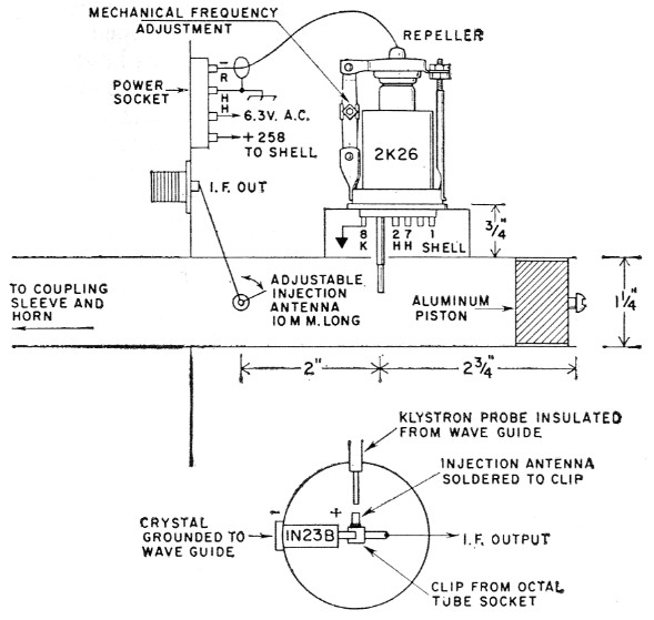
Fig. 2. Details of the klystron oscillator and crystal mixer used in the 5650 Mc transceivers.
The waveguide assembly is mounted in an aluminum chassis 3 × 5 × 7 inches with 2¾ inch of the guide protruding from the end of the box. The power socket and coaxial fitting are also mounted on this end. This permits a short lead for the i.f. output between the crystal and the coaxial fitting.
The horn antennas are simply 10 inch tin funnels soldered to short sections of 14 inch copper pipe. A piece of aluminum tubing just large enough to slide over the pipe is used as a coupling sleeve between the r.f. section and the horn. This sleeve is slotted and clamped with auto radiator hose clamps. These horns have low power gain and were made for test purposes. A horn antenna about 21 inch long, with a 12½-inch throat diameter would have a gain of approximately 50, whereas the test horns have a gain of less than 10.
No special precautions need be taken in laying out the power supply or wiring it. The only critical area in the control unit is the microphone amplifier and modulator. Wiring from the microphone input through to the repeller terminal on the power socket should be short, and shielded to prevent hum pickup. Hum pickup should also be avoided in the a.f.c. circuitry.
Adjustment and operation
Upon completion of the two r.f. sections and control units, the klystrons may be set to the approximate frequency and checked for oscillation. Adjust the klystron tuning strut to almost full height. Set the crystal injection probe to about a 45 degree angle. Turn on a.c. power and warm up the heater about 5 minutes. Set the meter-selector switch to the crystal position and the manual frequency control to approximately 90 volts; a.f.c. switch off; microphone gain off. After five minutes, turn on the high-voltage switch, rotate the frequency control from approximately 60 to 100 volt, and if all is well there will be an indication of oscillation on the meter. Adjust for maximum current, which should occur with the frequency control set near 90 to 100 volts with most tubes. Next, adjust the tuning piston for maximum crystal current. Then adjust the injection probe for 0.4 mA by varying its angle with respect to the klystron antenna probe. This crystal current is recommended for the best signal-to-noise ratio.
At this point, switch the r.f. sections and repeat above steps on the second r.f. section, using the same control unit. After both r.f. sections have been checked out, test the other control unit. Now the matter of measuring frequency should be taken up. If you can beg or borrow a wavemeter that reads the 5650 Mc band you have no problem. I did have a problem, and had to measure the wavelength in space. By using a variation of the Lecher wire principle(1) a crude wavelength measure can be made. Mount a 1N23B crystal about 1 inch above a cardboard shoe box or similar nonmetallic support. Connect a sensitive microammeter to it. Aim the open end of the waveguide at the crystal from about a foot away. Place a small metal plate behind the crystal and vary the position of the plate until a null is observed on the meter. Mark the position on the box, move the plate away from the crystal to the second null, and mark this position. Repeat for a third null. The distance between the first and third lines is one full wavelength. By careful measurement and double checking, reasonable accuracy can be obtained.
![]()
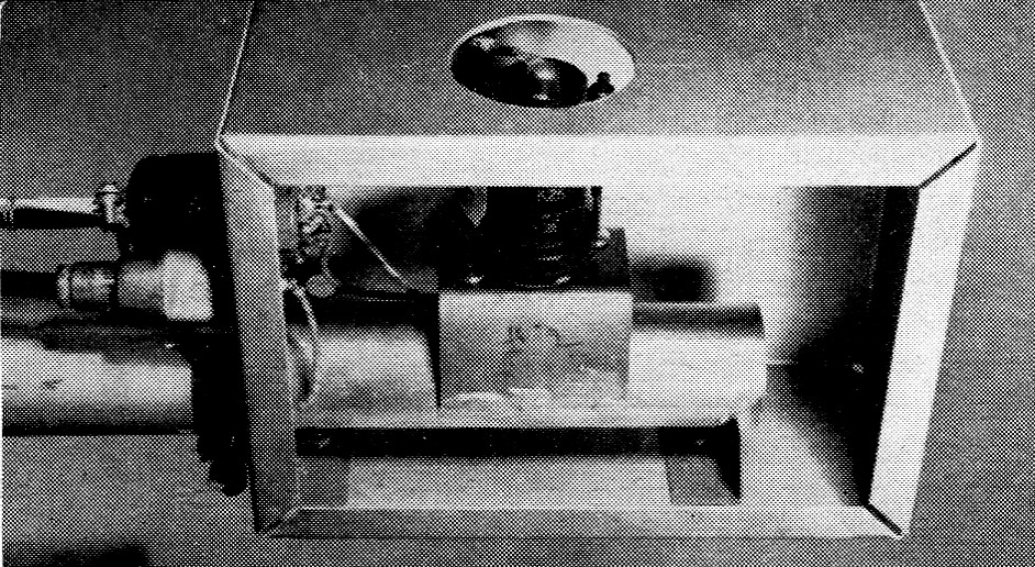
Closeup of the r.f. assembly of the 5650 Mc transceivers, showing the method of mounting the klystron on the tubular waveguide.
After checking the wavelength to make sure that both units are in the band, try them for transmission and reception. The transceivers may be set up on opposite sides of a room, with the horn antennas attached and facing each other, and the control units connected. Set both i.f. units up on the same frequency. Warm up the klystron heaters about 5 minutes, then turn on power switch. Crystal current will indicate oscillation. If both klystrons happen to be mechanically tuned close to the same frequency (within 50-100 Mc) it should be possible to tune in the opposite transceiver by varying the frequency potentiometer carefully. A strong signal should be heard and the limiter should read about -30 µA. With the a.f.c. switch off and the meter switch in the discriminator position, the needle will swing erratically plus and minus, depending on how good the voltage regulation is in each power supply. When the a.f.c. switch is on, this erratic movement should cease and it should be possible to set the discriminator to zero with the frequency potentiometer. If the signal refuses to lock hi, the discriminator output polarity is wrong. In this case, it is only necessary to switch r.f. sections between the control sections to provide correct polarity. With the signals locked in you can check the modulator. Plug in the microphone and open the gain control. Audio will be heard on both receivers simultaneously. Quality will be excellent, especially if the power supplies have low hum level. The a.f.c. in one unit will maintain a constant frequency separation, so there is no need to have the other a.f.c. switch on.
For maximum antenna coupling, vary the waveguide length in the sleeve and adjust for a shallow dip in crystal current. After this adjustment, readjust the crystal injection probe for 0.4 mA crystal current. When placing transceivers in operation, have one r.f. unit horizontal, the other vertical. This places each crystal in the proper plane for the incoming signal. (Unit 1 klystron probe vertical, unit 2 crystal vertical; unit 2 klystron probe horizontal, unit 1 crystal horizontal.) This arrangement was used because it made it possible to control oscillator injection.
The intermediate frequency selected is not too important; any frequency from 30 to 100 Mc can be used. If 88 Mc is selected and one klystron is on 5900 Mc, the other klystron must be on 5812 Mc to insure operation inside the band. The 2K26 will oscillate at about four points when varying the repeller voltage from zero to -108; the correct mode of oscillation is at 90 to 100 volt. The frequency potentiometer will provide about 25 Mc tuning range on each side of peak output, with about half power at the 25 Mc points.
For optimum output, crystal currents should be at peak when the correct i.f. is obtained. If not, the mechanical tuning of one klystron should be shifted carefully and the repeller voltage adjusted until these results are obtained.
The crystal injection probe is adjusted by bending the output conductor where it leaves the guide. Once the adjustment is made, it will hold for some time. Improvements can be made in the crystal circuit, such as tuning it to the signal and intermediate frequencies. These refinements are not necessary, and can come later.
Modulator and A.F.C. information
According to published data on the 2K26, its frequency will vary 1 Mc with a 1 volt change in repeller voltage. Therefore, if a frequency swing of plus or minus 75 kc is considered desirable for the i.f. system in use, varying the repeller voltage 0.075 volt at an audio rate will effect full modulation. The audio voltage coupled from the 6AT6 cathode to the repeller series resistor is more than enough to do the job.
Electrical tuning is accomplished by varying the potentiometer on the regulated negative supply, thereby varying the voltage applied to the repeller series resistor. Automatic frequency control is effected by varying the repeller voltage in accordance with changes in output voltage of the discriminator in the f.m. receiver. The regulated negative supply is in series with the cathode voltage of the 6C4 a.f.c, tube, so any change in cathode voltage due to a varying grid voltage raises or lowers the repeller voltage. When the change in repeller voltage is of the proper polarity, the intermediate frequency will be maintained constant.
Effectiveness of the automatic frequency control can be checked by placing an intermittent heavy load on the a.c. line and observing the discriminator reading. The needle will swing off center and then return to zero as the frequency is corrected. Action may be improved by using 2 to 4 megohm and 0.1 µF in the second section of the a.f.c. filter. If the receiver has an "S" meter, this may be used instead of limiter metering.
Short distance tests were conducted with the help of Joe Koenig, K8EUY. The larger unit was used as a fixed station and the smaller as a mobile, powered by a homemade inverter. Future plans are for construction of larger and better horn antennas and also new r.f. units to operate in the 3500 and 10,000 Mc bands. Low-power klystrons are available on the surplus market for operation in those bands.
Notes
- This technique is illustrated on the cover of September 1948 QST. Print from original negative $1.50 postpaid.
C.J. Prechtel, W8DRR.