The inverted V-shaped dipole
With sunspot activity on the skids, the 40 and 80 meter bands are going to assume increasing importance in DX work over the next few years. The simple antenna described here has been giving a good account of itself in many installations for both long- and short-haul work.
An effective antenna for 40 and 80.
For the past eight years, the author (and several others at his suggestion) have been using a type of antenna that has consistently brought better signal reports on 80 and 40 meter, in comparative tests, than more conventional types such as the ground-plane and horizontal and vertical dipoles. Furthermore, it actually costs less and is easier to put up than most other types commonly used for these lower-frequency bands. Other advantages are that it can be put up in a smaller lot than required for a horizontal dipole, and the antenna does not have to support the weight of a feed line, which is quite a consideration where coaxial line is used.
Resonant length
Fig. 1 shows the simplicity of the inverted V-shaped dipole. It consists of a half-wave dipole supported at the center, with the two halves dropped downward at an angle from the horizontal. Sloping the wires in this manner causes an increase in the resonant frequency so that a somewhat longer length of wire (approximately 5%) is required for the same frequency. However, the resonant length will be influenced by other factors in each individual case, so the length should be adjusted experimentally for each installation. This can be done with an s.w.r. bridge in the feed line, the length of the antenna being adjusted for minimum s.w.r. at the desired frequency.
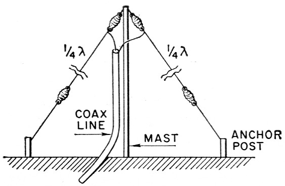
Fig. 1. The inverted-vee dipole. The length should be adjusted as described in the text.
Impedance and band width
Sloping of the wires also results in a decrease in the feed-point impedance. A 50 ohm line will usually give a closer match than a 70 ohm line. While the angle of slope is not critical, but it will be found that as the angle between wires becomes sharper, the Q increases and the band width is narrowed. This narrowing can be limited by using three- or five-wire conductors or "cages" rather than single wires for the antenna (see photographs).
Directional properties are not pronounced, although there is some slight emphasis at right angles to the direction of the wire.
Two-band operation
For 40 meter operation, a separate similar dipole may be used. It may be connected in parallel with the 80-meter dipole at the feed point and both may be fed with a single coaxial line. The 40-meter dipole may be run in any direction relative to the 80 meter dipole, but if the two dipoles are run at approximately right angles, as shown in Fig. 2, they will have less interaction and may also be used as the upper set of guy wires for a mast support.
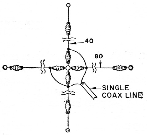
Fig. 2. Top view of a two-band arrangement. Dipoles for 80 and 40 meters are connected in parallel and fed with a single coaxial line.
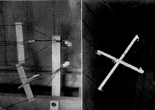
Details of cage construction for broad banding elements. Spreaders are paraffined wood.
Support
As with any other type of antenna, the inverted V-shaped dipole should be elevated as high as possible. It is quite feasible to use a tree as a support since most of the branches will be near the low-potential portion of the antenna. The elasticity of nylon cord makes it a desirable material for anchoring the ends of the dipoles. And, if a tree is used, the time-tested system of pulleys and counterweights may be used to advantage. The Cesco Dri-Fit connector is an ideal type of center insulator where coax feed is used. It has a heavy eyelet for attaching the hoisting rope.
A tower or pole supporting a beam antenna for the higher frequencies has been used as the center support for this antenna with no apparent impairment of the performance of the beam. However, it is probably a good idea to keep the apex 5 or 6 ft. below the array.
Feeding
In feeding this antenna, the same transmission-line problems must be considered as with any other antenna. Although coax feed can and has been used, the workable band width of any system using coax feed is limited if losses from a high s.w.r. and problems in loading are to be avoided. The author prefers tuned open-wire line not only because losses when working over the full width of the band are minimized, but also because it maintains a balanced system.
Results
In numerous tests in which it was possible to switch antennas instantly, the inverted V-shaped dipole has invariably proved to be superior to a half-wave horizontal dipole at the same height, a vertical dipole and a ground plane, which were used for comparison. It is assumed that the sloping results in a lower angle of radiation. K7GCO, running 600 watt input, has been frequently reported by DX stations as one of the top signals from the W7 area on the 40 meter phone band. DX on 75 meter includes an S8 contact with EL4A in Liberia - a fair haul from Washington on any band. Others who have tried this antenna have reported similar results, while some have found it the answer in covering shorter distances (100 to 1,000 miles) where both vertical and horizontal antennas had previously been required to assure reliable coverage.
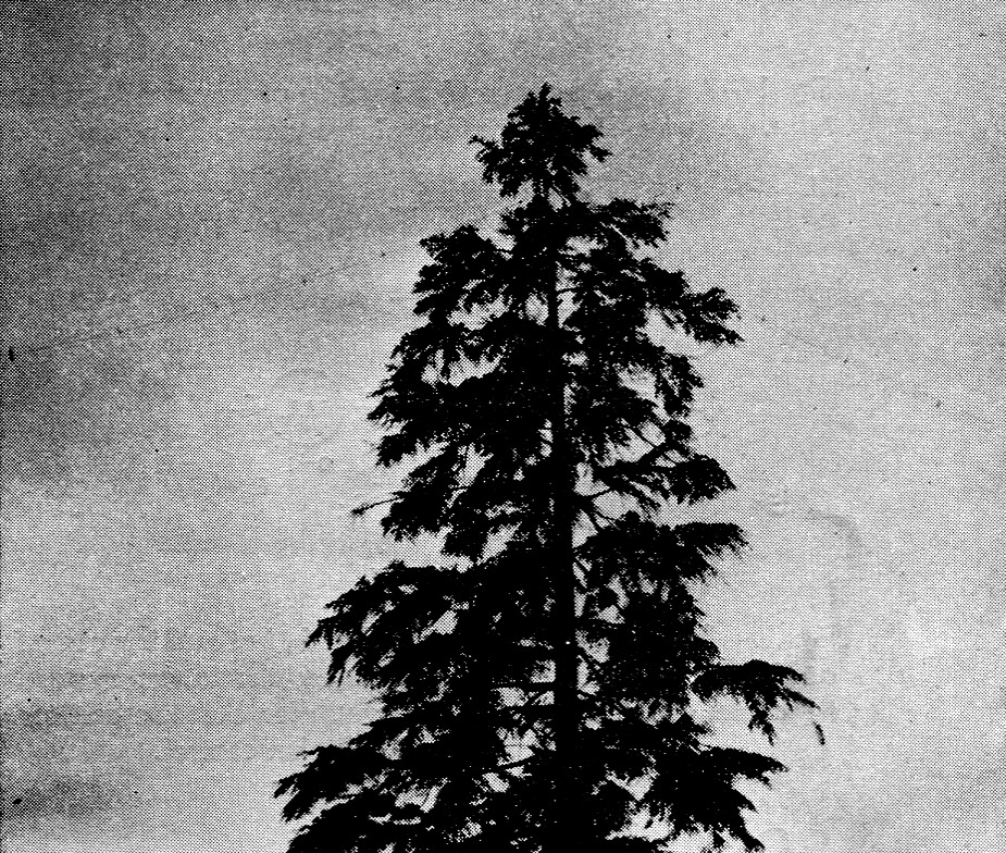
K7GCO's antenna is shown here supported by a tall tree. Multiwire elements are used to increase band width.
Some work has been done at K7GCO on a fixed-direction beam using two elements of the inverted-V type, one as a director, supported at the ends of a 15 ft boom on a tower. Results so far have been encouraging on both 40 and 80, although the spacing is rather close for 80.
Ken Glanzer, K7GCO.