Tuning (S) meter circuits
Principles of operation and adjustment.
While the familiar receiver S meter is one of the most prevalent instruments found in ham shacks, it is often the least understood. This article discusses some of the basic types including their adjustment and calibration.
Notice that the title places emphasis on tuning-meter circuits, not S meter circuits. The original intent in such devices was not to compare signal strengths but to serve as an aid in tuning a signal in "on the button." It is more or less by accident that tuning-indicator meters happen to be so placed in receiver circuits that they may also indicate relative signal strength. But the accuracy in absolute terms is very much open to question.
Using the tuning meter as an S meter gives rise to a wide variation in interpretation. First, there is no accepted standard of signal input voltage vs. S meter reading. The S meters of some receivers show a reading of S9 with a 50 µV input signal, others with a 100 µV signal, and still others have "Scotch" meters requiring a 200 µV input signal for an S9 reading. Also, S meters do not operate directly from the signal input voltage, but only indirectly after the signal has been amplified. Thus the deflection depends upon receiver gain, and the receiver has yet to be built that will provide uniform gain over the width of an amateur band, let alone from band to band! Under the circumstances the average S meter . provides little more accuracy than might be obtained by listening to the signal and comparing it with the standard S chart. Nevertheless, human nature being what it is, the perverse use of the tuning meter as an S meter is here to stay. It soothes the operator to hear the classic report, " Your signal is 40 dB over S9" which, translated literally, means "Your signal has 10,000 times the power of an extremely strong signal"!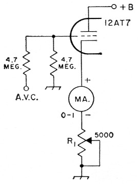
Fig. 1. A simple S-meter circuit using a separate S-meter tube. A wire-wound resistor is recommended for R1.
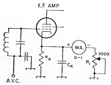
Fig. 2. Circuit similar to that of Fig. 1, but making use of an i.f. amplifier tube controlled by the a.v.c. system. RK and CK are the normal i.f. amplifier cathode resistor and bypass. R1 is a 3000 ohm control.
S meter circuits
S meter circuits vary in detail, but all of the conventional types operate indirectly from the varying bias voltage developed in the receiver's a.v.c. system. With the remote cutoff tubes used in the r.f. and i.f. amplifiers of most receivers, the relationship between signal-input voltage and the a.v.c. voltage developed results in linear S-meter deflections in terms of dB only at low signal levels. At high signal levels, the variable-gain characteristic of the remote-cutoff tube destroys the linearity so that the scale of the S meter becomes compressed at the high-signallevel end. This is not necessarily a disadvantage; in fact, it may be considered desirable since the effect is to spread the calibration out over the most-used portion of the scale.
The meter itself cannot be connected directly to the a.v.c. line because the load would impose a virtual short circuit across the line. Some form of amplication is required. This amplification can take place through a separate a.v.c. amplifier or through a tube already serving as an r.f. or i.f. amplifier. Although the latter method is more economical, S meter circuit values must be tailored so as not to interfere with the normal function of the amplifier. The separate a.v.c. amplifier is independent of such considerations, and its design is therefore more straightforward.
Simple Systems
Fig. 1 illustrates one of the simplest S meter circuits. In this circuit, the grid of a separate S-meter tube is connected to the a.v.c. line so that it receives biasing voltage in accordance with the variations in a.v.c. voltage with signal strength. The meter, a 0-1 d.c. milliammeter, and a variable resistor are connected in series in the cathode circuit. The series resistor, R1, is adjusted so that the meter reads full scale with no signal. A signal at the input of the receiver will cause an increase in the a.v.c. bias which, in turn, will cause a decrease in the cathode current of the meter tube and the meter pointer will be deflected toward the zero-current mark. This is a "backward-reading" circuit, the pointer moving from right to left with an increase in signal strength. Since most operators prefer that the movement be from left to right, receiver manufacturers using backward-reading S-meter circuits use special meters which have a deflection opposite to that of conventional milliammeters, or mount a conventional miiliammeter in an inverted position on the panel. The meter in this circuit cannot be pinned by a strong signal; it cannot be driven beyond the zero-current point.
A similar circuit applied to an i.f. amplifier tube, rather than to a separate S-meter tube, is shown in Fig. 2. Here the meter operates from the voltage drop across the cathode resistor of the i.f. amplifier. This voltage drop varies in accordance with the variations in cathode current caused by the changing a.v.c. bias. The meter is initially set at full-scale reading with no signal by adjustment of the series resistor, RI. The operation is essentially the same as that of the circuit of Fig. 1. However, the a.v.c. voltage never drives the i.f. amplifier to zero cathode current, so the pointer will only approach the zero-current point on the strongest signals.
Forward-Reading Circuits
An S-meter circuit that may be adjusted for "forward reading" is shown in Fig. 3A. In this circuit, the plate resistance of an i.f. amplifier tube is used in one arm of a resistance bridge. The equivalent circuit is shown in Fig. 3B where Rp represents the tube plate resistance. With the amplifier tube out of its socket, R2 is adjusted so that the meter reads full scale. Then, with the tube replaced, R1 is adjusted until the meter reads zero current with no signal. When a signal is applied to the input of the receiver, the increase in a.v.c. bias increases the value of R,, the bridge is unbalanced and current flows in the meter circuit. The meter cannot be pinned because the initial adjustment is for full-scale deflection with the i.f. amplifier tube cut off - a condition that will only be approached by the bias normally developed in the a.v.c. system.
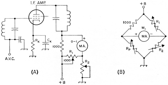
Fig. 3. Forward-reading bridge S meter circuit. R1 is a 1000 ohm control. R2 should have a maximum resistance in ohm approximately 1000 times the plate voltage. RK and CK are the normal i.f. amplifier cathode resistor and bypass. B shows the equivalent circuit in which the plate resistance of the i.f. tube is represented by R.
Another variation of the bridge circuit is shown in Fig. 4A with its equivalent in Fig. 4B. In this circuit, the varying bias of an i.f. amplifier tube is applied to the grid of VIA whose plate circuit serves as the variable arm of the bridge. The plate circuit of V1B is used in one of the fixed arms, but its plate resistance may be set to the required fixed value by adjustment of its grid bias by means of R2. With no signal, R2 is first adjusted to balance the bridge (zero current reading). Then, with plate voltage removed from VIA, R1 is set to bring the current reading to full scale. With plate voltage reconnected to V1A, the meter should deflect in accordance with the signal level.
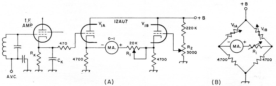
Fig. 4. Differential S-meter circuit. This circuit is similar to the bridge circuit of Fig. 3, but employs a separate S-meter tube. V1B is used as an adjustable resistor in one arm of the bridge, as shown in the equivalent circuit of B. R1 and R2 are composition controls. RK and CK are the normal i.f. amplifier cathode resistor and bypass.
Calibration
The most accurate method of calibrating an S meter involves the use of a signal generator with calibrated attenuator. The manual r.f. gain control should be set at some desired reference point. The S meters of most manufactured receivers are calibrated with the r.f. gain control wide open. A choice should be made as to the signal input voltage that will correspond to an S9 signal. With a signal of this magnitude applied to the input of the receiver, the S9 point on the meter should be established. Other S points on the scale may be plotted in reference to the S9 mark, inscribing an S point each time the signal input voltage is cut in half. For instance, if a 100 µV signal is chosen for S9, then a 50 µV signal will cause an S8 reading, a 25 µV signal an S7 reading, a 12.5 µV signal and S6 reading, and so forth. This gives readings of 6 dB per S point. If it is desired to have the readings above S9 in steps of 10 dB, then a 10 dB point will be marked each time the input voltage is increased by a ratio of 3.16. Thus the 10 dB point above S9 will be the point registered on the meter when the signal input voltage is 316 µV, and the 20 dB point will be registered with a 3.16 × 316 = 948 µV signal, and so on. Yes, indeed, a 40 dB-over-S9 signal is quite potent.
Not many of us have access to elaborate measuring equipment, and the following method will serve almost as well for practical purposes. Set the r.f. gain control so that the meter reads just above zero with no signal. Tune the receiver to different signals on the air. A weak signal accompanied by a high level of background noise (hiss) should give a reading of about S3. A fairly good signal accompanied by a medium amount of background noise should give a reading of about S5. A moderately strong signal accompanied by very little noise should give a reading of about S7. A strong signal with no background noise should give a reading of about S8.
From the preceding discussion of circuit operation, it is evident that a change with age in resistor values, or in the condition of tubes, not only those directly in the S meter circuit but those in the gain-determining stages and in the a.v.c. circuit as well, will affect the accuracy of the meter. So perhaps an ear calibration by chart isn't so inaccurate after all!
Marvin M. Tepper, W1YCV.