813s in grounded grid
KW amplifier for the DX bands.
Over the past several months we have had numerous requests for information on a grounded-grid amplifier using the popular type 813. We are pleased to present this nicely turned out version by W6FLT.
The amplifier was designed to be used with any transmitter of the 100 watt output class serving as the driver. In my own case, the driver happens to be the Heath Apache, thus the similarity in panels. The amplifier operates at 400 mA and 2250 volt. The total power input to all stages feeding power to the antenna (this includes the final stage of the driver) is one kilowatt. Since my interest lies in only the higher-frequency bands, the design has been confined to the 14, 21 and 28 Mc bands. Thus far, the amplifier has been used on c.w. only, but it should be equally satisfactory as an s.s.b. linear when suitably adjusted for this type of operation.
With a low-pass filter and antenna coupler, there is no TVI, even though the TV antenna is almost directly under the 14 Mc beam. This has not been the case with any grounded-cathode transmitter that has been used previously at this station, which is located in a fringe area.
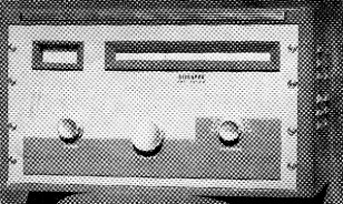
The panel of W6FLT's kilowatt grounded-grid 813 amplifier is designed to match the Apache transmitter which is used as the driver. Controls from left to right are for the band switch, plate tank capacitor and loading capacitor.
Circuit
The circuit, shown in Fig. 1, is quite conventional for a grounded-grid amplifier. The control grids are not grounded directly, but are suitably bypassed instead to permit the use of grid-leak bias. The screens are grounded directly, placing them in parallel with the control grids so far as r.f. is concerned. The filaments are isolated from ground for r.f. by the bifilar choke RFCI. The tank coil in the pi-network output circuit is tapped for the three bands. A.c. and plate-voltage leads are filtered for v.h.f. A fan provides circulation of air around the 813s.
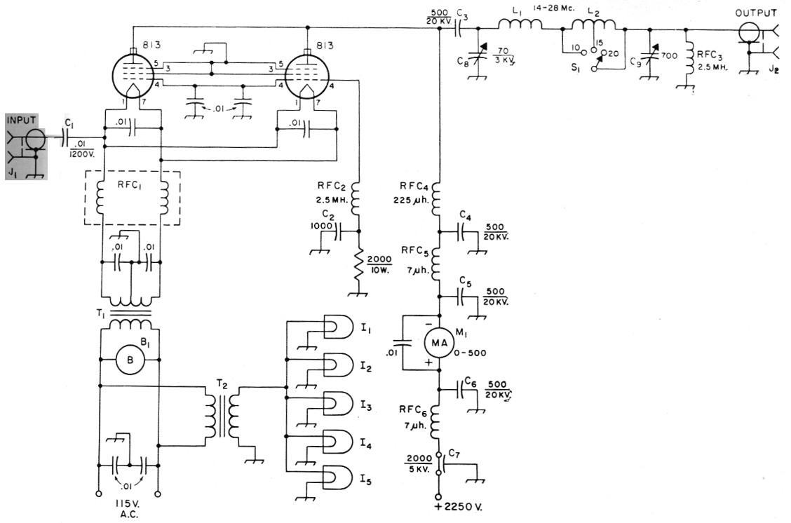
Fig. 1. Circuit of the 813 grounded-grid amplifier. Capacitances less than 0.01 µf are in Pf. Capacitors not listed below are disc ceramic.
| B1 | Fan and motor (Elmar Electronics*). |
| C1 | Mica. |
| C2 | 500 volt disk ceramic. |
| C3,C4,C5,C6 | TV "Doorknob" ceramic. |
| C7 | Feed-through type (Sprague 47P16). |
| C8 | 3000 volt variable (Johnson 155-9). |
| C9 | Dual b.c. replacement-type variable, 350 pF per section, sections in parallel. |
| I1-I5 inc. | 6.3 volt dial lamp. |
| J1,J2 | Chassis-mounting coax receptacle (S0-239). |
| L1 | 3 turns 1/2-inch copper strap, 1 inch diam., 1¾ inches long. |
| L2 | 9 turns ¼ inch copper tubing, 2¼-inch diam., 4 inch long, tapped at 2½ and 6 turns from output end. |
| M1 | D.c. milliammeter. |
| RFC1 | Barker & Williamson FC-15. |
| RFC2 | 125 mA r.f. choke (National R-100S). |
| RFC3 | 50 mA r.f. choke. |
| RFC4 | National R-175-A. |
| RFC5,RFC6 | V.h.f. choke (Ohmite Z-50). |
| S1 | See text. |
| T1 | 10 volt 10 amp. filament transformer (Merit P-3146, Stancor P-6461 or similar). |
| T2 | 6.3 volt 1 amp. filament transformer (Thordarson 21 F08). |
Construction
The chassis measures 12 by 17 by 2 inches and is spaced 1¼ inch behind the 10½ × 19 inch panel to allow room for the dial assembly, band-switch drive and dial lamps. The shielding enclosure is 12 by 13 by 8¼ inches, leaving a 4 inch space at the left-hand end of the chassis for the filament and dial-lamp transformers. The back and sides of the enclosure are made of Reynolds perforated aluminum sheet. The right-hand end and back are extended so that they may be fastened to the apron surfaces of the chassis. The bottom edge of the remaining side is bent over to form a lip by which this side may be secured to the surface of the chassis. The front edges of the two sides of the box also have lips for fastening to the front wall. The latter is a sheet of solid aluminum attached to the front apron of the chassis. The cover is secured by a series of 4-36 machine screws tapped into ¼ inch square brass rod running around the top edge of the enclosure. Screw holes are spaced 2 inch apart.
The placement of components within the shielding compartment may be determined from the top-view photograph. The tank capacitor is mounted directly on the chassis and is placed so that its shaft is central in respect to the panel (not the front wall of the enclosure). The tank coil and band switch are mounted close to the capacitor. A separate coil section is used for 10 meters, as indicated in Fig. 1. The switch is driven by the left-hand panel knob by means of a metal band and a pair of pulleys. The band is made from ¼ inch shim stock obtained from an automobile supply store. The pulleys are 1½ inch in diameter and the band is pinned to the pulleys to keep it from slipping. The switch was taken from a BC-375 tuning unit but I have had no trouble with an ordinary receiving-type ceramic switch which I used in another amplifier running at 800 watts input. Copper braid, ¼ inch wide, is used for the coil tap leads.
The shaft of the pi-network output capacitor, mounted to the right, runs within an inch or so of the tank coil, so a section of insulated rod was inserted between the capacitor shaft and the panel control shaft.
The sockets of the 813s are submounted flush against the under side of the chassis with Pins 3 and 5 grounded to the nearest mounting screws. he filament choke is mounted close to the ckets and the capacitors shunting the filaments are connected directly at the socket terminals. Bypasses are grounded at the nearest point on the chassis. The hardware was removed from the -175-A choke and the unit mounted directly on e chassis. The fan is mounted on rubber shock ounts to reduce noise and vibration.
The r.f. input connector is set in the rear edge of the chassis at the closest point to the tube kets. The output connector is mounted above chassis in the rear wall of the enclosure at a point close to the loading capacitor. A Millen safety terminal is used for the high-voltage connection and a barrier strip for the a.c. connections. High-voltage test-lead wire covered with copper braid is used for the high-voltage wiring. Connections between the top of the plate r.f. choke and the plates of the 813s are made with M-inch copper braid.
The shaft of the tank capacitor extends through to the center knob on the panel. This shaft carries a 534-inch dial pulley mounted between the panel and the shielding enclosure. The dial scale is drawn on white paper and then glued to a plate of 346-inch aluminum measuring 2M by 11 inches. The plate is mounted on the front of the shielding enclosure on Yi-inch spacers. A small pulley is mounted at each end of the plate and the dial cable runs from the large pulley on the tank-capacitor shaft over and across the small pulleys and back to the drive pulley. The pointer, salvaged from an old radio receiver, is fastened to the dial cable. The diameter of the drive pulley restricts the movement of the pointer to less than the full dial length, so the 0 and 100 points on the scale are a distance from the ends of the dial plate. The escutcheons, control knobs and a meter-mounting bracket were obtained from Heath as replacement parts. The panel decoration is a strip of 1/8 inch Masonite cut to match the one on the Apache.
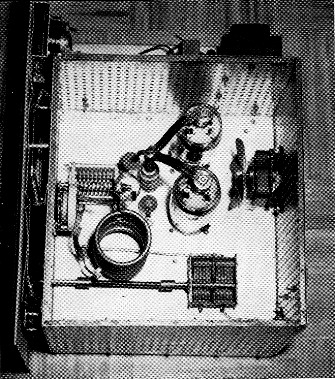
Interior view of the 813 grounded-grid amplifier.
The meter is in the high-voltage lead to the plate and therefore the meter should be recessed and insulated from its mounting. The meter was insulated from the metal mounting bracket by applying empire cloth, holding it in place with plastic tape.
The dial scale is illuminated by three dial lamps, one in the center and one at each end; two lamps illuminate the meter.
Adjustment
The tuning procedure to be used with a grounded-grid amplifier differs from that usually followed in adjusting a grounded-cathode stage. Some form of output indicator is a necessity. Although a point will be found where the plate current dips with tuning of the output tank circuit, this may not, and probably will not, be the point of maximum output.
Also, the output will be found to vary widely with the driving power applied. I use my standing-wave indicator set in the "forward" position as an output indicator. Alternatively, a field-strength meter will serve.
The length of the coax between the output of the driver and the input of the amplifier should be kept as short as practicable, since the input impedance of the amplifier changes considerably with drive and loading adjustments, making it virtually impossible to maintain a proper termination for the coax line.
It is advisable to reduce plate voltage during the initial tune-up procedure, although the plate power input can be held to a safe value by keeping the driving input down. Plate voltage on the amplifier should be turned off while the driver is first adjusted to resonance with its output coupling reduced to minimum. Set the amplifier tank capacitor at about half maximum capacitance and the output capacitor at about 2/3 maximum (assuming a 50 ohm load). Now apply plate voltage to the amplifier. The idling current at 2500 volt, and without excitation should be about 70 ma. Increase the coupling to the driver until the amplifier plate current increases to 150 or 200 mA. Adjust both tank and loading capacitors for maximum output. These controls interlock, requiring a process of juggling until the maximumoutput settings are found. Now the driver coupling can be increased until the input to the driver is at maximum rating (assuming a driver in the 100 watt-or-so-output class). Simultaneously, the loading of the amplifier should be readjusted so that the sum of the inputs to the driver and the amplifier does not exceed 1000 watt. With the Apache loaded to an input of 180 watt, the grid current to the amplifier runs about 40 mA and the voltage across the grid leak is 80 volt. Using the standard methods of checking, no tendency toward parasitic oscillation was found and no other difficulties have been met in operating the amplifier on any of the three bands.
W.R. Stangel, W6FLT.