A simple wavemeter for use in coax lines
Easy to build novice band checker.
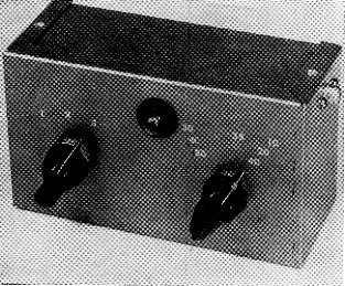
The completed wavemeter ready for use. The knob on the left is the band-switch control, the dial lamp is at the top center, and the knob for C1 is at the right.
A Common complaint from Novices is that they get on the air, call and call, but don't get answers. In many cases the transmitter and antenna seem to be working OK and a local station or two may have been worked, but nothing out of town.
Believe it or not, one of the easiest mistakes to make is to tune your rig for what you think is the right band but your fundamental signal is actually going out on some other band. The local station? He is probably copying a harmonic or spurious emission. If you don't believe Novices can get on the wrong band just listen around 20 meter - you'll hear plenty of Novice call signs. Also, the 7400 kc region is "popular" with some Novices.
These aren't harmonics we're discussing, but are instances where the transmitter is actually tuned to these bands or frequencies. It is true that the band switch on your transmitter may be set correctly, but unfortunately many rigs, both commercial and home-built, can be incorrectly tuned up. The result is a signal going out on the wrong frequency.
Fortunately, there is a very simple method for checking to make sure you are transmitting on the right band. This consists of using a calibrated absorption-type wavemeter to check your signal. The unit described in this article can be built in an evening and only costs a few dollars. In addition to checking the band, the unit also serves as an output indicator that shows you when r.f. is in the feeders on the way to the antenna.
One of the problems in using an absorption wavemeter is that you must have relatively tight coupling between the wavemeter and the circuit with r.f. in it. Most transmitters these days are built into cabinets that have fairly tight shielding to prevent harmonic radiation. Trying to couple a wavemeter to the tank circuit in such a rig could prove to be quite a chore. In addition, many hams- use a coax feed line from the rig to the antenna and here again it is well-nigh impossible to couple the wavemeter to the line. These problems are eliminated with the wavemeter described here. The unit is a part of the coax line and can-be left in the line at all times.
The wavemeter
The circuit of the wavemeter is shown in Fig. 1. It consists of a pair of - coils, L1L2, in series with a variable capacitor, C1, and a dial lamp, I1, which serves as the indicator. S1 is a single-pole, three-position switch which is used to short out L2 and a portion of L1 for changing bands. In the open (first) position of Si the 80-and 40-meter bands are covered. In the second position, the range from 40 through 20 can be covered. The third switch position takes care of 20, 15 and 1.0 meters.
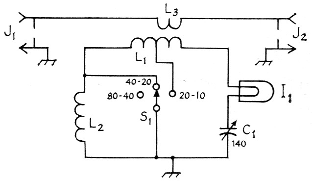
Fig. 1. Circuit diagram of the wavemeter.
| C1 | 140 pF variable (Hammarlund HF-140). |
| I1 | Dial Lamp; up to 25 watts input, No. 48 or 49 (60 mA). 25-50 watt input, No. 47 (150 mA). 50-75 watt input, No. 46 (250 mA). |
| J1,J2 | Phono connector. |
| L1 | 15 turns No. 20, 16 turns per inch, 1-inch diam. (B & W Miniductor 3015). |
| L2 | 22 turns No. 24, 32 turns per inch, 1-inch diam. (B & W Miniductor 3016). Tap for 7-14 Mc range is at junction of L1L2; tap for 14-28-Mc. range is 5 turns from I1 end of L1. |
| L3 | Coupling loop; see text. |
| S1 | Single-pole three-position switch (Centralab type 1461). |
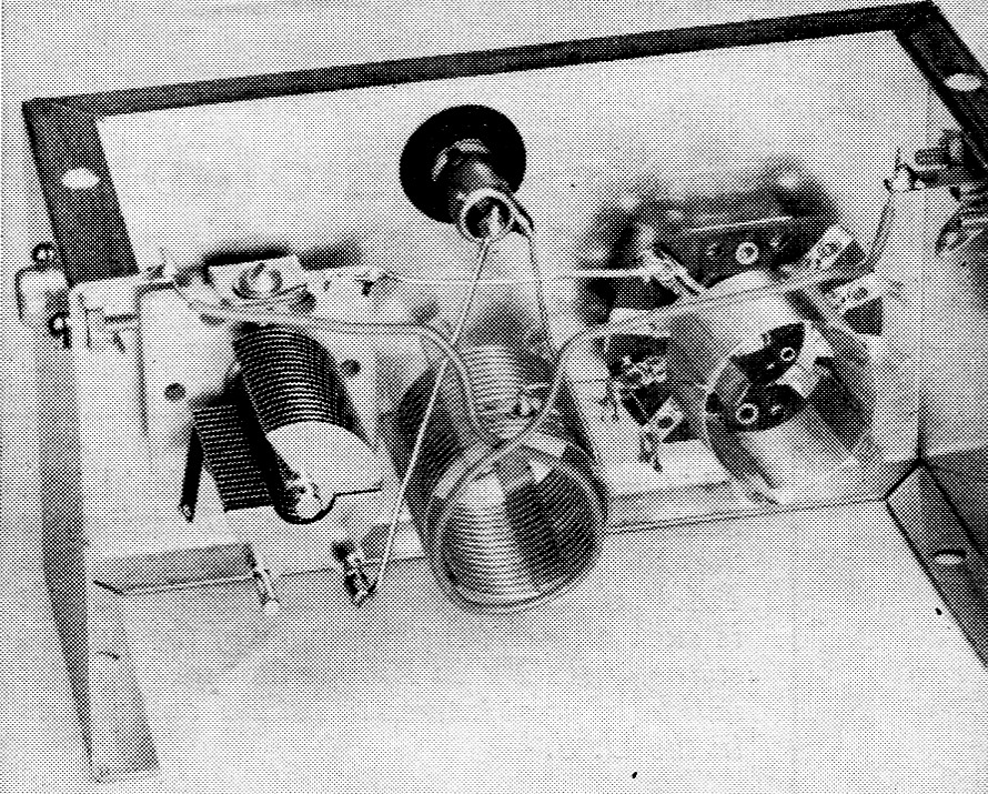
Inside view, showing the arrangement of the components. L1 is mounted between C1 and S1 and L2 is directly over S1. A double-pole, three-position switch is shown in the photo but only one pole is used as specified in Fig. 1.
When the entire inductance, L1L2, is used, the 3.5 Mc end of the 80 meter band falls near the maximum-capacitance setting of C1 (plates nearly fully meshed) and the 7-Mc. band is near minimum capacitance. Advancing S1 to the next position shorts out the L2 portion of the coil and 7 Mc. appears near maximum capacitance and the 14 Mc band near minimum. In the last position of S1, 14 Mc is near maximum and the 28 Mc band is close to minimum, with 21 Mc. near the middle of the range.
Coupling from the coax line is accomplished via a single loop, L3, in the line, the loop being positioned near one end of L1.
How to make it
The wavemeter is built into a 2_1/8 × 3 × 5¼ inch Minibox. L1 and L2 consist of sections of Miniductor coil stock. One section is mounted over Si and is held in place by its own leads and the other section is positioned between S1 and C1 (see back view). Two phono jacks, J1 and J2, are mounted on either end of the box and the pickup line, an 8 inch length of insulated wire, is connected between the two jacks. A single loop (L3), the same diameter as L1, is made in the line, the loop being positioned about ¼ inch away from the end of L1.
The dial lamp is held in place by a 3/8 inch rubber grommet mounted on the front of the box. The leads from the arm of S1 and the stator of C1 are soldered to the base and shell of the lamp. This eliminates the need for a lamp socket. Check Fig. 1 for the correct lamp size for your power input.
When arranging and mounting the components be careful not to place any of them too close to the edges of the box, otherwise the bottom of the box won't fit.
How to test and use the wavemeter
Connect the wavemeter to your transmitter, through J1, using a couple of feet of RG-58/U or RG-59/U coaxial cable. Tune up on 80 meters. Connect a dummy load, such as a lamp bulb, to J2 so you don't have a signal going out on the air. Switch Si to the position that leaves the entire coil, L1L2, in the circuit. Carefully tune Cl until the dial lamp lights up. The dial lamp should light near the maximum capacitance setting of C1. Make a note of the knob setting and then tune up on 40 meters. Using the same switch position, the lamp should light near minimum capacitance of C1. Leave the transmitter tuned to 40 and switch S1 to the next position. Tune C1 near maximum and the bulb should light up again. Change bands to 20 (if you're a Novice licensee you have to use a dummy antenna on this and the 10-meter band) and find the C1 setting for this band as indicated by the light. Follow the same procedure for next switch position, making notes of the settings of C1. Finally, replace the dummy by the coax line to your antenna and you're all set.
As an alternative to depending on the transmitter, the wavemeter can be calibrated if you have a grid-dip meter or can borrow one. Here is the way to do it:
Couple the grid-dip meter to L1, set the meter to the middle of the 80 meter band (3750 kc) and then tune C1 for the grid dip. Make a note of the setting of C1 and proceed to 7 Mc, following the same system. You can quickly determine the C1 settings for the rest of the bands with the grid-dip meter. The information you have from your notes will enable you to make a dial that can be mounted under the mounting nut of C1.
In using the wavemeter as an output indicator all you have to do is set Si and C1 for the right band and tune your rig for maximum brilliance of the dial lamp. With the unit mounted alongside the rig you will always have a check on the band plus visual indication of power in the coax line.
This gadget is primarily for the Novice who can't be sure where he is in the radio spectrum. However, some General or Conditional Class hams may be interested in installing the wave-meter in their stations. For higher power levels than 75 watts it is possible that the circuit as described could burn out dial lamps. It is a simple matter to reduce the amount of coupling from the line by reducing the size of the pickup loop or bending it away from L1.
Lewis G. McCoy, W1ICP.