The "Budget" vertical on 20 meter
Correspondence indicates a sizeable response to the author's earlier article describing the construction of a vertical 40-meter antenna from an accumulation of empty beer cans. The addition of the simple matching circuit described here permits operation on the 20-meter band, also. Included are some helpful hints on maintenance.
Method of seeding the 7 Mc beer-can radiator on 14 Mc.
With a DX appetite stimulated by the performance of the "Budget" vertical antenna(1) on 7 Mc, it wasn't long before the author started entertaining thoughts of joining the "Big guns" on 20 meter.
A quarter-wave antenna on 40 will resonate as a half-wave radiator on 20 meters. However, the bottom end of a half-wave vertical is a high-voltage point and therefore an impedance step-up is necessary between coax line and the antenna. The impedance-transforming device used by the author consists of a simple parallel tuned tank circuit tuned to 14 Mc. and connected between the bottom end, of the antenna and ground. The coax line is then tapped onto the tank coil at a point that provides a match to the line, as shown in Fig. 1.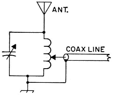
Fig. 1. Circuit for feeding the quarter-wave 7 Mc vertical antenna as a half wave on 14 Mc. Tank-circuit values are discussed in the text.
To permit operation on 20 or 40 as desired, the switching circuit of Fig. 2 may be used. The author uses a d.p.d.t. ceramic-biise knife switch. However, a well-insulated antenna relay may be used for remote switching.
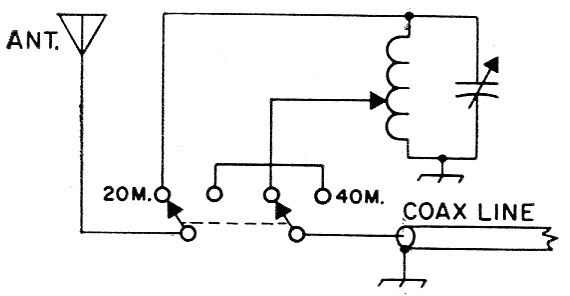
Fig. 2. Switching circuit for 7 or 14 Mc operation. See text for details of components.
The matching circuit
The L-C ratio of the tuned tank circuit is not critical. A high-C circuit will provide some additional discrimination against harmonics. However, don't carry the C too far or you will end up with a coil so small that it will be difficult to adjust the tap. Also, a high-C circuit will reduce the band width. In deciding on the dimensions of the coil and its conductor size, a good rule to follow is to make the coil an approximate duplicate of the 20-meter tank coil in your transmitter. The plate spacing of the capacitor should also be about the same as you find in your transmitter tank capacitor. The maximum capacitance should be somewhat greater than required to tune to resonance with the coil to make allowance for the effect of possible antenna reactance. For the coil, I used 10 turns of 1/8 inch copper tubing, with 1/16 inch between turns, wound on a 1¼ inch form. The capacitor has a maximum capacitance of 100 pF and transmitter plate spacing. The combination should be enclosed in some sort of weatherproof box.
Adjustment
After connecting the tank circuit between the base of the antenna and the ground system, ground the outer conductor of the coax line and spot-solder the inner conductor onto the coil at about 2½ turns above ground. Set the capacitor at about 80 pF if you use the coil described above. Otherwise, check the circuit with a g.d.o. and set the tuning to approximately the center frequency of the desired portion of the 20 meter band.
Although one can use his transmitter and a reflected-power meter for adjustment, the author used a grid-dip oscillator and an s.w.r. bridge both built from the ARRL Handbook. The "load" end of the s.w.r. bridge is connected to the station end of the coax line. A one- or two-turn loop is attached to the input connector of the s.w.r. bridge, and the g.d.o. is link-coupled to this loop. Set the g.d.o. to the desired center frequency in the 20-meter band.
Now get someone to adjust the capacitor at the antenna slowly while you watch for a minimum reading on the s.w.r. bridge. If a complete null does not result, the tap on the coil should be moved a quarter of a turn at a time in one direction while you watch for the null. If the minimum reading goes higher, move the tap in the opposite direction. If adjustment of the tap does not result in a complete null, the setting of the capacitor may have to be touched up. When the null has been obtained, the s.w.r. bridge may be removed and the coax line connected to the transmitter. Yo a are now all set to go on 20 meters with a low angle of radiation.
15 meter
The antenna may also be fed directly with coax line (no matching network) on 15 meters. The antenna will be operating as a 34-wave vertical radiator on this band and, here too, most of the energy should be radiated at a low angle.
Maintenance
Last, but not least, the author would like to make a few comments on the mechanical attributes of this antenna. It has weathered all storms over the last five years without damage. A direct hit with a baseball kinked one of the cans a couple of summers ago, so I had to scare up a replacement - not a very serious problem!
The original aluminum paint lasted about two years. When the labels on the cans began to show through, the XYL rounded up the mast-lowering team (our two sons and me) and we gave the beer-can vertical a new coat. She said that I had a worried expression when we started to lower the contraption which, however, soon evaporated in a smile. It seems that it is as strong as ever. It should prove something about the mechanical abilities of solder.
Several of the readers of the original article complained of difficulty in making the solder stick to the cans. In answering these inquiries I advised the liberal application (slop it on) of noncorrosive soldering paste. After the job is completed, the excess may be removed very easily with acetone or other solvent.
The buried aluminum radials have corroded quite badly, although they are still useful. However, I plan to supplement them with a new set of copper radials when the antenna comes down for repainting as soon as time and weather permit. The performance of this antenna on 20 has been as satisfactory as it was previously on 40 and the author has now achieved prominence by qualifying as a member of DXCC.
Notes
- Czerwinski, "Budget 7 Mc vertical antenna," QST, November, 1955.
W. Pete Czerwinski, W2JTJ.