The nuvistor as an r.f. amplifier at 144 Mc
Radical departure in tube design pays off in v.h.f. service.
Hams who attended the ARRL National Convention in Galveston in 1959 got their first look at a wholly-new idea in vacuum-tube design. They got the look, that is, if they looked closely enough as they passed the RCA booth at the convention. The Nuvistor is so small that it has to be displayed in blown-up fashion. This small size is just one of the features that make the Nuvistor of interest to the v.h.f. amateur. It also has high transconductance, low lead inductance, low power consumption and exceptional ruggedness and uniformity to recommend it. Best of all, it is moderately priced, and it will soon be readily available.
Working K1IJB, Sandy Hook, Conn., recently on 144 Mc, we learned that he was using a Nuvistor as an r.f. amplifier ahead of his 2-meter converter. It had a measured noise figure of around 2 dB, slightly better than the 417A cascode job with which it was being tested. When adjusted for lowest noise figure, it delivered about 20 dB gain. This in a single neutralized-triode r.f. stage of simple design, with a relatively inexpensive tube, was of more than ordinary interest. We wasted no time getting down to Sandy Hook to learn more of this first amateur use of the Nuvistor in our area.
It will be seen from the circuit diagram that the amplifier is a conventional neutralized stage, similar to the first half of the familiar cascode, except that the cathode is grounded directly, rather than through a bias resistor. The Nuvistor (commercial tube number: 6CW4) operates at low plate voltage. If the supply voltage is much over 70, the dropping resistor R1 should be adjusted in value to keep the voltage on the plate to about 70, and the input to less than the rated 1 watt plate dissipation. At 70 volt and 8.1 mA the transconductance is 12,7 mA/V. Thus its performance at 144 Mc is better than all but the very best tubes, and because of the uniformity of the Nuvistor results of this order are likely to be more readily obtained than with random 417As.
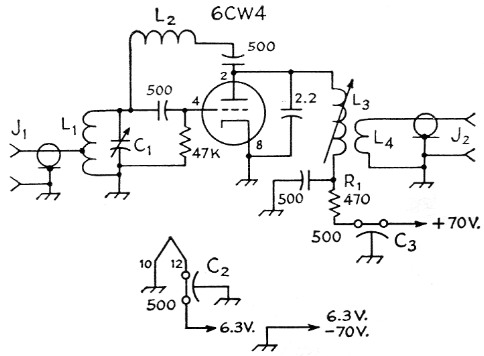
Fig. 1. Circuit of the Nuvistor r.f. amplifier. Capacitor values in pF.
| C1 | Sleeve-type trimmer, 1.5 to 7 pF. |
| C2,C3 | Feed-through bypass, 500 pF. |
| J1,J2 | Coaxial fitting, BNC type. |
| R1 | 470 ohm, ½ watt. With higher supply voltage adjust value to give 70 volt on plate. |
| L1 | 5 t. No. 20, ¼ inch diam., spaced wire diam. Tap about 2 turns, or for lowest noise figure. |
| L2 | No. 26 enamel close-wound on high-value ½ watt resistor, about 3/8 inch. Adjust turns for neutralization; see text. |
| L3 | 5 t. No. 22, spaced wire diam., on 1 inch iron slug form. |
| L4 | 1 t. insulated hookup wire around bottom of L3. |
K1IJB neutralized his amplifier by the time-honored method of disconnecting one heater lead and adjusting the inductance of L2 for minimum feed-through of a strong test signal. Size of the winding was critical to about plus-or-minus 1 turn. The input circuit is adjusted for lowest noise figure, and the plate circuit for maximum gain. No further adjustment of L2 was needed after the initial feed-through minimum was obtained.
The metal cover of the Nuvistor has two extensions that key it to its socket, maintaining correct pin alignment. The socket is available as Cinch Mfg. Co. No. 133-65-10-001.
The input capacitance of the 6CW4 is 4.2 pF, or less than half that of a 417A. This should make use of conventional circuits easy at 220 Mc, and possible at 420. Work on converters for these bands is planned for the very near future, and results will be published as soon as available. Meanwhile, this example of what one ham was able to do with the Nuvistor on 144 Mc stirs optimism that here, in a simple way, is a means to lower noise figures than we have attained previously with inexpensive tubes and conventional circuitry.
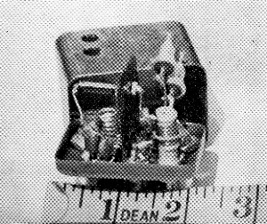
The Nuvistor 2 meter amplifier built by K1IJB. Shield partition separates input and output circuits, with input at the left. Note position of the neutralizing winding, perpendicular to the input coil.