Low-frequency parametric amplifier
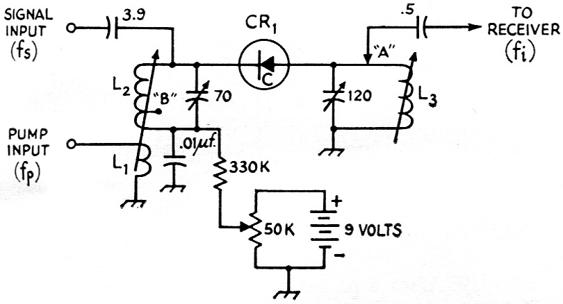
Fig. 1. "Educational" low-frequency parametric amplifier. Unless otherwise indicated, capacitances are in pF.
CR1 semiconductor capacitor diode (see text).
The circuit shown in Fig. 1 is a simple 10 Mc parametric amplifier that can be made to function with only simple test equipment. I used it to get the feel of parametric amplifiers before jumping in at the deep end with a v.h.f. or u.h.f. model.
A grid-dip oscillator is used to resonate the tuned circuits. Coil L2 is resonated to the input signal frequency, fs, and L3 to the idler frequency, fi. The pump is coupled into the signal tank by means of a four-turn link, L1, wound on the cold end of L2. An r.f. signal generator having a 50 ohm output impedance is used as a pump generator. Output from the device is coupled to the receiver from point "A" or "B". Almost any of the inexpensive capacitor diodes seem to work in this circuit. I used a Vari-Cap with a nominal capacitance of about 47 pF.
Most of the various parametric amplifier effects described in the literature may be observed by using different combinations of signal, pump, and idler frequencies. Some interesting frequency combinations in Mc. are:
| fs | fp | fi |
|---|---|---|
| 10 | 14 | 4 |
| 10 | 14 | 24 |
| 10 | 20 | 10 |
Richard F. Burns, W9NVC.