Stability with simplicity
An easy-to-build v.f.o. with cathode-follower output.
There are certainly no complicated circuits or constructional features in this v.f.o., just straightforward application of time-tested principles - which probably explains why it works so well. We put it through its paces when W2YM brought it up to the QST lab, and can heartily recommend it to the most critical user.
As a clincher, several other units have been built to the same design and have duplicated the original's performance.
In my 30 years as a radio amateur I have probably built as many v.f.o.s. as anyone else. Because most of them did not meet the standards that I wanted, I kept on seeking the ultimate. Although this v.f.o. may not be, strictly speaking, the ultimate, its performance has been exceedingly good; for this reason I thought others might be interested in this simple design.
Circuit details
Examination of the circuit, shown in Fig. 1, reveals that basically this oscillator is of the hot-cathode Colpitts type. The 3.5- to 4-Mc. range is spread over practically all of the tuning dial. The effect of changing tube capacitance is minimized by use of a voltage divider consisting of three capacitors, C4, C5 and C6, with the tube connected across two of them. The use of fairly large capacitors (0.001 µf.) at C5 and C6 almost completely swamps out the effect of the tube capacitances. The radio-frequency choke, RFC1, is used to obtain a d.c. path for the cathode current of the 12AU7-A oscillator. The output of this v.f.o. is obtained from a cathode follower (second triode unit of the 12AU7-A) to minimize the effect on the oscillator of changing output-circuit conditions. The liberal use of silver-mica capacitors assures fairly stable temperature characteristics.
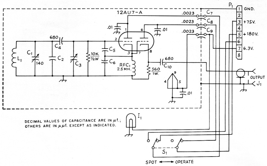
Fig. 1. The v.f.o. circuit. 0.01 µF capacitors are disk ceramic. Components outside dashed line are external to the case.
| C1 | 140 pF variable (Hammarlund MC-140-S). |
| C2 | Approximately 100 pF; see text. |
| C3 | 25 pF air padder (Hammarlund APC-25). |
| C4 | 680 pF, silver mica. |
| C5,C6 | 1 nF, silver mica. |
| C7,C8,C9 | Feedthrough type (Centralab FT-2300). |
| I1 | 6.3 volt pilot lamp. |
| J1 | Coaxial connector, chassis-mounting type. |
| L1 | 14 turns No. 20, 16 turns per inch, 1 inch diameter (B & W 3015). |
| P1 | 8-prong (octal) cable connector, male. |
| S1 | D.p.d.t. toggle. |
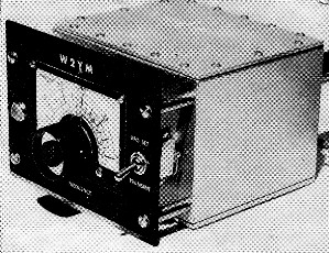
The panel of the v.f.o. is supported on metal pillars to provide space for the dial mechanism, since the tuning capacitor is firmly mounted on the front side of the shield box. Note the heavy (1/8 inch thick) top and bottom plates for stiffening the aluminum box.
Mechanical details
As in any variable-frequency oscillator, the mechanical considerations are probably as important as the actual electrical circuit utilized. Therefore, considerable attention has been paid to the mounting of the oscillator components. The complete oscillator is built in a 4 × 5 × 6 inch aluminum utility box. The oscillator tube is mounted horizontally on the back of this box, together with the power and output connectors and the 25 pF frequency-setting capacitor. The advantage of this mounting arrangement is that the heat developed by the tube does not have as much effect upon the circuit components as it would if the tube were mounted in a conventional manner inside the box. The tuning capacitor should be a high-quality, two-bearing capacitor. In this oscillator, a Hammarlund MC-140-S capacitor was used.
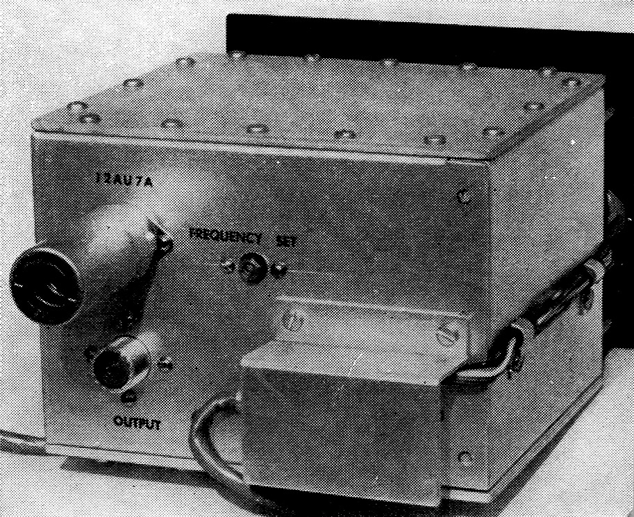
External connections, brought out through feedthroughtype capacitors, are covered with a small aluminum "awning" to prevent accidental shock. Wiring to the "zero-operate" switch and dial lamp is cabled and clamped to the side of the box.
Maximum rigidity of the oscillator circuit is obtained by use of a special aluminum bracket formed from one of the original box covers, as shown in Fig. 2. The box cover material is soft aluminum and can easily be bent with the aid of wood blocks and a vise. A hardwood block and hammer are used to make the bends square and sharp. The bracket is bolted securely to the front and back of the oscillator box; thus it not only supports the circuit components but also aids considerably in stiffening the box itself. To aid in fitting the variable capacitor, the holes for the mounting feet are slotted, and in assembly the shaft nut is first tightened to the side of the box and then the 6-32 screws for the feet are tightened. Special clamps to hold the coil are cut from thin Lucite sheet in strips ¼ inch wide and 2½ inches long. Holes are drilled at the ends of the strips so that they can be bolted to ½ inch standoff insulators and, in assembly, the coil is clamped between the two Lucite strips to provide a sturdy coil mounting. The silver-mica capacitors must be mounted so that there is no possibility of any motion. Again, half-inch standoff insulators are used as tie points, as can be seen in the top view. For further stiffening of the unit, new covers were cut from 1/8 inch aluminum panel stock and fastened to the box with liberal use of self-tapping screws.
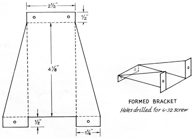
Fig. 2. Mounting bracket for the tuned-circuit capacitor and inductor.
Although the particular arrangement shown uses a National MCN dial mounted on a small panel and bolted to the v.f.o. box with 1½ inch metal bushings, any dial and panel arrangement can be used. The v.f.o. box is sturdy enough so that it could be completely supported from the panel.
Feedthrough-type bypass capacitors are provided for making power-supply connections to the v.f.o. This arrangement not only provides handy terminals, but also reduces the radiation from the v.f.o. The small aluminum bracket that covers these connections is used to minimize shock hazard.
The tolerances of the three capacitors connected between coil and grid, grid and cathode, and cathode and ground are such that some experimentation with the value of C2 may be necessary. Combinations have been found where the value of C2 is as low as 56 pF or as high as 120 pF.
If the v.f.o. is installed in a well-ventilated location away from heat sources, no temperature compensation should be found necessary; however, if such installation is not possible, a combination of temperature-compensating capacitors and zero-coefficient silver mica capacitors can be used for C2.
Voltage amplifier
The output from the cathode follower is only 1½ to 2 volt, and it may be necessary to amplify this output to a level of 10 to 30 volt, depending upon the transmitter to be used. Almost any receiving-type pentode can be used for the amplifier tube. Because the amplifier stage is a convenient place to key the transmitter, a 6DT6-A is used as a combined amplifier and keyer tube in the circuit shown in Fig. 3. The 6DT6-A is similar to the popular 6AU6, but has a high grid-No. 3-to-plate transconductance. It was originally designed for use in TV and f.m. receivers as a sound demodulator, and has the advantage of complete plate-current cutoff with only a few volts negative on grid No. 3. Also, because grid No. 3 is a high-impedance element, the key-click filter need be nothing more than a simple RC network. A 0.02-pf. capacitor and a 220 kΩ resistor are used in circuit. For "harder" keying the capacitor value should be reduced, and for "softer" keying it should be increased. The plate-load resistor shown provides an output of about 15 volts, the value required to drive the transmitter used by the author. If more output is required, the value of the plate-load resistor can be increased to approximately 5600 ohms. The highest output is obtained by use of a 2.5 mH radio-frequency choke in place of the plate-load resistor.
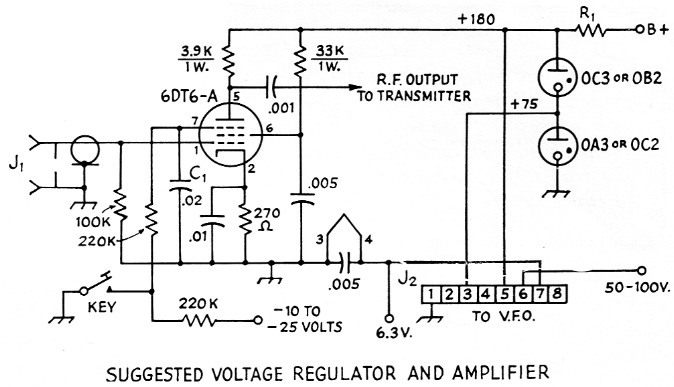
Fig. 3. Suggested circuit for keyed amplifier and voltage regulator. This circuit usually would be incorporated in the transmitter or be built as a separate unit. Capacitors may be ceramic or mica as desired.
| C1 | Approximately 20 nF, paper. Increase capacitance for softer keying, decrease for harder keying. |
| J1 | Coaxial connector, chassis-mounting type. |
| J2 | Octal socket. |
| R1 | 25 watt slider type; value dependent on voltage of supply source. Adjust for 30 mA through VR tubes with key open. |
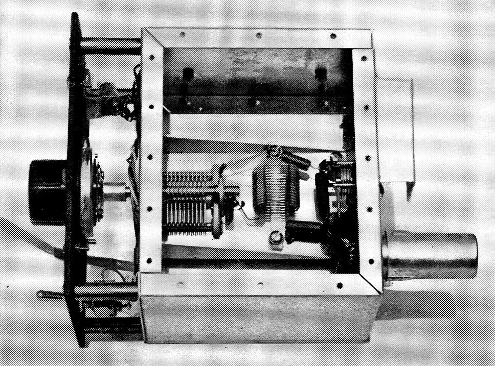
The interior layout is very simple and clean. The tuning capacitor and coil are mounted on the central bracket, which also forms a bridge between the front and back of the box for further stiffening. The small padder for adjusting the frequency calibration is on the rear wall of the box.
Plate voltage for the v.f.o. is obtained from a regulated supply using a pair of VR tubes, as shown in Fig. 3. Voltages used are 75 volt for the oscillator and 180 volt for the cathode follower and amplifier. No appreciable shift in oscillator frequency is observed between key-up and key-down conditions. Lead No. 6 of the power cable may be connected to any convenient voltage source of 50 to 100 volt (in my station layout this voltage is obtained from the receiver) so that the v.f.o. may be spotted on frequency without turning on the transmitter. On 80 meters the signal from the v.f.o. without cathode follower is just enough to be used for spotting purposes; on the higher-frequency bands it is necessary to energize the cathode-follower section and the 6DT6-A amplifier.
Performance considerations
Those interested in circuit details may wonder why a higher-transconductance tube was not used so that the oscillator grid might be tapped farther down on the tuned circuit. Such a tube was tried, but caused instability. Experiment indicated that the medium μ, medium gm tube worked best in all cases. Other tubes that can be used for the oscillator-cathode follower are 6SN7-GT, 6CG7, 5692, and 6189. The last two are, of course, premium tubes, and are intended primarily for critical industrial applications.
The performance of the v.f.o., as mentioned before, is exceedingly good. With the coil and capacitors used, the tuning range is nearly linear from 3495 to 4005 kilocycles. The frequency-set capacitor, C3, will shift the oscillator frequency about 35 kc. The measured frequency drift after about 3 minutes warm up was less than 20 cycles in 2½ hours.
George D. Hanchett, W2YM.