Meter reading by sound
The simple instrument described here by W6PIV not only enables a sightless operator to tune his transmitter to resonance, but also makes it possible for him actually to "read," with reliability, current values on the scales of milliammeters in many types of equipment.
Audio device for the sightless ham.
Various gadgets have been devised to aid the ham without sight in tuning his transmitter, and many are doing very well with them. Most of these devices use a voltage picked up at an appropriate point in the transmitter circuit to change the tone of an audio oscillator in accordance with the change in voltage as the transmitter is tuned. Most sightless hams are able to memorize the particular tone that corresponds to normal transmitter loading.
More recent designs(1) have made use of transistors to reduce bulk and weight and thus render the instrument more convenient to use. However, transistors are sensitive to changes in temperature, and while the operator may have no trouble in determining resonance in his transmitter, he cannot be sure that transistor drift has not shifted the oscillator pitch corresponding to normal loading. Thus, he may be underloading or overloading without being aware of it.
The unit described here includes a simple comparator-type calibrator which automatically compensates for any drift due to temperature effects or component aging. Furthermore, it is not necessary for the operator to memorize audio tones. He can actually "read" current values to an accuracy of 5 per cent or better on a Braille-calibrated dial.
Circuit
The system shown in Fig. 1 was developed by W6CKV and the author, and has been used successfully by several of their sightless friends. The operating voltage is taken from the drop across the shunted 0-1 ma. milliammeter commonly found in most transmitters, manufactured or homebrew. This voltage (0.03 to 0.1 volt depending upon the internal resistance of the meter) is fed into a transistor d.c. amplifier whose output voltage controls the frequency of an audio oscillator also employing a transistor.
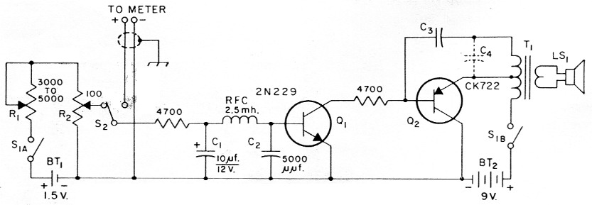
Fig. 1. Circuit of the audible meter reader. Resistances are in ohm and fixed resistors are ½ watt composition.
| BT1,BT2 | See text. |
| C1 | Electrolytic (see text). |
| C2 | Mica or ceramic. |
| C3 | 0.002 to 0.1 µF, paper or ceramic, capacitance depending on transformer used and tone desired. |
| C4 | Approx. 0.02 µF, paper (see text). |
| LS1 | 2 inch p.m. speaker. |
| Q1 | N-p-n transistor (Sylvania). |
| Q2 | P-n-p transistor (Raytheon). Sylvania 2N1265 is also suitable. |
| R1 | ½ watt control, screwdriver-adjusted. |
| R2 | ½ watt control, linear taper (Centralab WW-101 or similar). |
| S1 | D.p.s.t. toggle switch. |
| S2 | S.p.d.t. slide switch. |
| T1 | Transistor output transformer, push-pull to voice coil. |
The voltage comparator consists of a simple voltage divider operating from a single dry cell. Potentiometer R2 is set at various points where its output voltages are the same as the voltage drops across the meter for various current readings. The Braille dial of the potentiometer is calibrated in any desired fractions of the full-scale meter value.
Then it is necessary only to adjust the comparator to obtain the same tone as produced with the meter connected, and read the comparator dial.
In the case of a multirange meter, the voltage drop across the meter terminals is the same for all current ranges, of course, so the operator must keep in mind the current range to which the meter is switched.
Construction
The construction of the unit is not critical. A typical layout for a 6 × 3 × 2 inch aluminum Minibox is shown is the sketch of Fig. 2. The cost of components should not exceed $12.00 or so. Capacitor Cl may not be needed. It was found necessary to use it with one of the transmitters we tried in order to eliminate hum in the speaker output. Also, C4 was needed in only one unit in which a miniature Japanese transformer was used. Units having larger transformers did not require it.
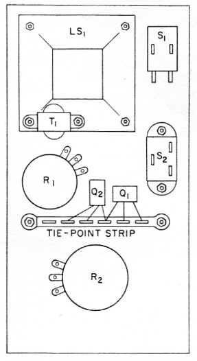
Fig. 2. Sketch showing suggested layout of component on one 3 × 6 inch face of a 3 × 6 × 2-inch aluminum box.
The wire leads for the meter connections should be shielded, either individually or as a pair, to prevent r.f. pickup or radiation. The shielding braid should be grounded at both ends, but both meter wires must be kept insulated from ground, of course. An opening will be found somewhere in most transmitter cabinets through which the cable can be passed to the meter. A three-prong connector for the cable will be found convenient if the unit is to be used with more than one piece of equipment.
Calibration of the dial of R2 is a simple matter. The transmitter is adjusted so that the meter reads full scale. R2 is set in the full clockwise position (maximum resistance between BT1 and the arm of the potentiometer). Then, while switching S2 back and forth from one position to the other, R1 is adjusted until the audio tones obtained in the two switch positions have the same pitch. For the remainder of the calibration, R1 remains fixed at this setting. The meter readings are reduced in the desired fractional steps, each time matching the tone obtained with the meter connected and the tone obtained with the switch in the opposite position by adjustment of R2. The dial of R2 is marked at each step. After the calibration is complete, a center punch can be used on the rear side of the dial to make raised markings on the front side which can be easily detected by Braille-sensitive fingers. In use, the matching of tones is surprisingly simple and adjustment is a matter of a few seconds.
Those who cbject to overloading the rig or detuning it for the short period of time required to get a meter calibration at full scale can disconnect the meter from the transmitter and obtain the deflection by means of a flashlight cell and a variable resistor of 1500 ohm or more in series connected across the meter. Alternatively, the calibration can be started with R2 and the meter at half scale, and the points above half scale plotted by estimation. Be sure to use a potentiometer with a linear taper if you want dial markings equally spaced.
For the batteries, seven penlite cells were used, six of them being connected in series for BT2. However, a 9 volt transistor battery may be found more convenient for the latter. The drain on either battery is 1 mA or less, so essentially shelf life may be expected.
Danger!
Before proceeding further, it should be emphasized that under no circumstances should the unit be used with meters that are connected in portions of the circuit that are at potentials of more than a few volts to ground. The meters in most manufactured transmitters meet this requirement, but there are exceptions, and no attempt should be made to use the unit without first referring to the circuit diagram of your particular transmitter. Also, make sure that no revision of the original metering circuit has been made. Of course, the metering system of any home-made transmitter should be examined carefully to make certain that the meter is at a point of low voltage to ground in all positions of the meter switch.
Adjustment and calibration
Before connecting the meter leads to the transmitter or other device, turn S2 to the meter position and short the meter wires. Then change the value of C3, if necessary (and the value of C4 too if used), to bring the oscillator frequency to a tone of a few hundred cycles. Then, with the meter cable connected to the transmitter, the tone should rise to 2000 or 3000 cycles when the meter is reading full scale.
Other uses
A standard 1 kΩ/V v.o.m. can be read accurately on voltage and current ranges by connecting the leads of the reader directly to the meter terminals. Calibrator R1 may have to be readjusted to match the comparator dial, since the meter may have a different internal resistance than the one in the transmitter. Resistance values may also be checked but with less accuracy, since in this use, the meter usually reads backwards and the scale is not linear.
The unit cannot be used with a 20 kΩ/V v.o.m. since the input resistance of the reader is not sufficiently high to avoid a significant shunting effect across the 50 µA meter.
The unit may be used with high-current meters (ammeters) if they are of the type having basic movements of 50 mA or so with internal or external shunts. However, many ammeters are of the unshunted type with relatively high internal resistances. The voltage drop across meters of this type may be great enough to temporarily paralyze the 2N229. The reader should not be used with meters of this type.
Notes
Ken Blaney, W6PIV.