Compression tuning in the v.h.f. range
How to squeeze a coil with a screwdriver.
Most every v.h.f. man knows about squeezing and stretching coils to vary their inductance. This method of tuning keeps the losses low, but it's a nuisance and you're never sure the circuit is still "on the nose" when all shields and chassis covers are in place. The scheme described here gives a fine adjustment even when the coil is inside a box and the power is on.
Every radio amateur, experimenter, and technician at one time or another needs high-quality coils for use in resonant circuits, transformers, discriminators, or filters in the very-high-frequency range. Although both fixed and permeability-tuned inductors can be obtained through radio supply houses, these may not have a sufficiently high Q.
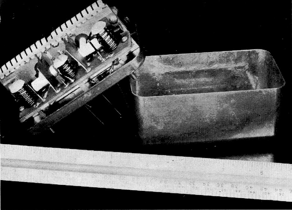
A v.h.f. filter using compression-tuned coils. The nylon tuning screws thread into the insulating material of a printed circuit board. In this case the screws were turned out on a lathe, but they could just as well be made by tapping a piece of polystyrene, screwing it onto a threaded rod and cementing it in place.
The best coil obtainable for the v.h.f. range is the simplest and least expensive - the air-core solenoid. At frequencies from 30 to 300 megacycles the quality factors of such coils are high, and it is not unusual to obtain a Q greater than 200. The coil should be wound on a cylindrical form with heavy wire (No. 17 or better). The coil can then be removed from the winding form since it is rigid enough to support itself. Coils wound with heavy wire have greater Q than those wound with small wire. Also, coils wound with a large diameter have a greater Q than coils wound with a small diameter.
The inductance of a solenoid is directly proportional to its cross-sectional area and to the square of the number of turns. Inductance is also more or less (depending on the relative length and diameter) inversely proportional to length. An easy way to vary the inductance of a coil is to alter its length by squeezing or stretching it. As the length is increased the inductance decreases, and as the length is decreased the inductance increases.
The squeezing operation may be done mechanically by placing a screw through the coil and a nut on the end of the screw. Both the screw and the nut should be of a dielectric material such as nylon or polystyrene. Although nylon hardware can be obtained, it is easier and cheaper to make your own hardware from polystyrene rods and sheets readily available from radio supply houses. Polystyrene rods can be threaded by holding them in a vise and carefully screwing on a suitable die. A 1/8 inch diameter rod threaded with a 6-32 die works well with small coils, and ¼ inch rod is recommended for larger ones. Nuts can be made by tapping a hole through polystyrene sheet. In mounting the compression screw on the coil base, it is good practice to tap the base to accept the compression screw and to cement the threads as well to prevent turning. Alternatively, the "nut" can be cemented to the rod and used as a screw head.
Fig. 1 shows three possible mounting arrangements. One end of the coil should be soldered to an eyelet in the base. The other end can slide through a contact in the base or be bent to form a sort of toggle joint, or a flexible lead can be used. The nut is turned, squeezing the coil and thereby adjusting it to the desired inductance. A fixed capacitance connected across the coil will constitute an adjustable resonant circuit. The resonant frequency can be measured with a grid-dip meter.
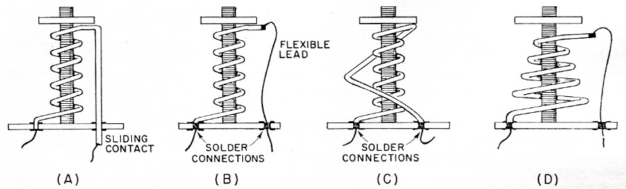
Fig. 1. (A), (B) and (C) show three ways of making connections to a compression-tuned coil.
In (A) the lead from the moving end passes through:a sliding contact in the insulating base.
In (B) a flexible lead connects the coil with an eyelet in the base.
Method (C) requires no sliding contact or flexible lead; the wire from the moving end is simply bent so as to flex with the coil.
(D) shows a conical-shaped coil which flattens when compressed. In all cases, the threaded rod can be cemented to the bottom plate and the top nut used for tuning, or the "nut" can be cemented to the rod and slotted to take a screw-driver blade.
Air coils other than solenoids can be used. For example, the conical-shaped coil of Fig. 1D flattens to a pancake when adjusted.
If a spring-type wire is used instead of soft copper wire, the coils will return to their original shape as the adjusting screw is loosened. Variable coils made of beryllium copper wire can be tuned many times without permanently deforming and can replace the greatest dust catcher of all, the variable capacitor. The price of this variable inductor is small compared to the capacitor, and because the inductance can be varied over a wide range, the band of frequencies covered by tuning the inductor is also wide.
Tuned transformers can be constructed as shown in Fig. 2. Two coils are used and they can be adjusted for required inductance and for required coupling. Tighter coupling is achieved by moving the coils closer to each other. The coupling governs the band width, and as the coils are moved closer the band width increases. As an illustration of typical values which can readily be obtained, a model was built and coupling was measured on a Q meter. The values of coupling obtained were 5 per cent for a coil separation of about ½ inch and 10 per cent for a coil separation of ¼ inch.
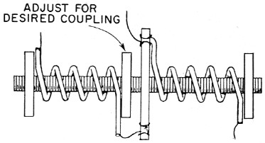
Fig. 2. A transformer with adjustable tuning and coupling using the compression principle. The nut just to the left of the central mounting plate sets the coil separation, and the end nuts are used for tuning.
The solenoid is also suited for use in filters in the v.h.f. range. Design formulas for low-pass, high-pass, band-pass, and band-reject filters are given in many electrical engineering texts and in reference books. The advantage of using the air-core coil in filters is that high-Q resonant circuits mean sharper cutoffs and steeper attenuation curves. Also, these coils may be adjusted so that the circuits resonate at the proper frequency, and there is no need for more expensive tunable capacitors. One must be careful in the physical layout of the filter. The coils should not be too close to each other or undesired coupling will result. This coupling would mean less attenuation in the stop band. Adjacent coils should be placed at right angles to minimize coupling. At v.h.f., short lead lengths and good grounds are a must.
At the Electronics Division of Westinghouse Electric Corporation, filters for some applications were designed and built with these adjustable solenoid coils. It was found that they are stable and hold their inductance extremely well under tough environmental conditions, passing shock and vibration tests with flying colors. The photograph shows a v.h.f. filter with five tuned circuits. No tunable capacitors are used.
The experimenter will no doubt find more applications for adjustable air-core inductors. He and his equipment will become more flexible by using them.
Mayer Savetman.