Screen protection and more
A foolproof system well worth its cost.
With the replacement cost of high-power tetrodes at $40.00 plus each, it is economically important to provide adequate screen protection. Much of the literature contains circuitry using a single relay in the screen supply lead as in Fig. 1. In theory, its operation is very simple and somewhat as follows: When the current through the relay coil reaches the pull-in point as a result of some adverse condition, the armature is expected to transfer the screen voltage to ground via resistor R2. If this sequence is followed, things are in fairly good shape as the resistor should draw enough current to hold the contacts closed in the grounded position. Then, with the screen at zero voltage, plate current will drop to a very low level - well under the plate dissipation rating of the tube. You should now have a chance to pull the main switch, run down the trouble and get back on the air.
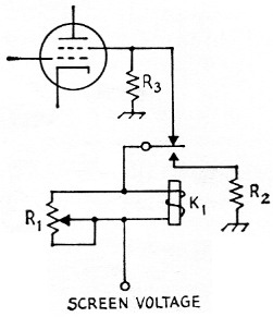
Fig. 1. A screen protective circuit which actually provides very little protection. Shunt resistor R1 is set so that K1 will throw if the screen Current becomes excessive. If all goes well, the screen voltage will be grounded through R2 which draws enough current to keep K1 transferred. Unfortunately, there is no current through K1 while its arm is moving from one position to the other. If the arm springs back before making contact, all you have is a buzzer! R3 is a bleeder (about 10,000 ohm) placed at the tube socket. It provides a ground return for the screen and prevents high voltage from developing there when K1 opens the supply lead.
But suppose you are modulating when the screen circuit opens and the plate current drops to a minimum. This results in no load for the modulator which, of course, is not good, except that the arc-over in the modulation transformer will alert you to the fact that something has happened. By that time it has! Since modulation transformers fall in the same price bracket as a pair of 4-400As, they, too, should be protected.
Relay engineers do not like this circuit anyway. Too much dependence is put on the inertia of the relay armature when the coil is energized.
It should be pointed out that when the movable contact breaks from its normally-closed position there is no current through the coil. The movable contact will tend to return to its normally-closed position and repeat the cycle. So you have only very marginal protection, if any - though you will probably have a pretty good buzzer.
The following describes a protection circuit which will take the entire rig off the air within milliseconds in the event of a screen overload. The circuit diagram, Fig. 2, includes a platecircuit-relay, K1, and a variable shunt resistor, R1, in the screen supply lead. When the contacts of K1 close, latching relay K2 is energized and opens the main plate supply line either directly or through a master control relay. The latch mechanism will hold the relay and the supply line open until a pulse to the reset coil via Si returns the circuit to normal. Coil voltage for K2 can come from a filament transformer or any power circuit that runs continuously.
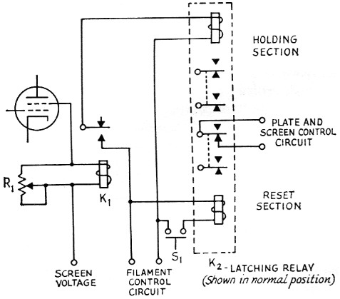
Fig. 2. The recommended circuit. Excessive screen current will operate K1, energizing the holding section of K2 which removes screen and plate voltage from the transmitter. K2 will remain transferred until S1 is closed momentarily and a pulse of current through the reset coil returns the contacts to their original position. The screen is returned to ground through the power supply bleeder, but a separate bleeder such as R3 in Fig. 1 can be added for insurance.
| K1 | S.p.d.t. plate circuit relay (Potter & Brumfield LB-5 with 2500 ohm coil). |
| K2 | Latching relay (Potter & Brumfield KB17AG and DG series; available with coils for various control voltages, a.c. and d.c.). |
| R1 | Sensitivity control for K1 (see text). |
| S1 | S.p.s.t. push-button reset switch, normally open. |
The relay specified for K1 is adjusted at the factory to pull in at approximately 9 mA. The shunt, R1, is used to vary this pull-in point to a current which will actuate the relay somewhere south of the maximum screen dissipation rating of the tube. The meter shunt formula in the Handbook will help determine an approximate value for the setting of R1. Then an exact adjustment can be made with the rig fired up.
K2 is a two-coil relay with a latching mechanism. A momentary pulse to one coil will transfer the contacts, and a pulse to the second coil will return them. The double-throw contacts on K2 are each rated at 10 ampere with 115 volt and a resistive load. With the two sets of contacts of the reset section connected in parallel, the relay will handle low-power transmitters directly. In high-power applications, the contacts should control a power relay in the main supply line. The hclding section contacts should not be paralleled with those of the reset section because of time lag, but they may be used to control auxiliary equipment, indicator lamps, etc. If arcing at the contacts is excessive, external arc suppression is recommended. See the Handbook under key clicks.
As with all your equipment, normal precautions should be exercised in installing the relays. Mounting should be such that the contacts are in a vertical plane so dust particles will pass through rather than deposit on the contacts. If voltages in excess of 500 or so are involved, the relays should be mounted on stand-off insulators, or at least on an insulated panel.
Incidentally, the same arrangement could also be used in the plate circuit (with an appropriate value of R1) to protect the plates against overload.
The author wishes to thank W9PNE and W6SAI for their very able advice and constructive criticism.
John A. Evans, W9HRH.