A Limited-space Antenna
Tunable system for 80 through 10.
Combining a vertical pipe and a horizontal wire, this simple antenna system is useful on five amateur bands. It includes a tuning and matching network that doesn't require switches or plug-in coils.
Many amateurs are restricted in the amount of space they have available for antenna installations, some even being confined to roof-top areas. This poses a problem when 80- and 40-meter operation is planned. The minimum over-all length of a horizontal antenna that should be used, for reasonable efficiency at these frequencies, is about 60 feet. When you must also make allowance for space for guy wires, the average city-lot or apartment dweller quickly runs out of room.
The antenna system described here requires very little space - even the roof of a small house is adequate. The system will provide fairly good multiband coverage - 80 through 10 meter - as the test model proved.
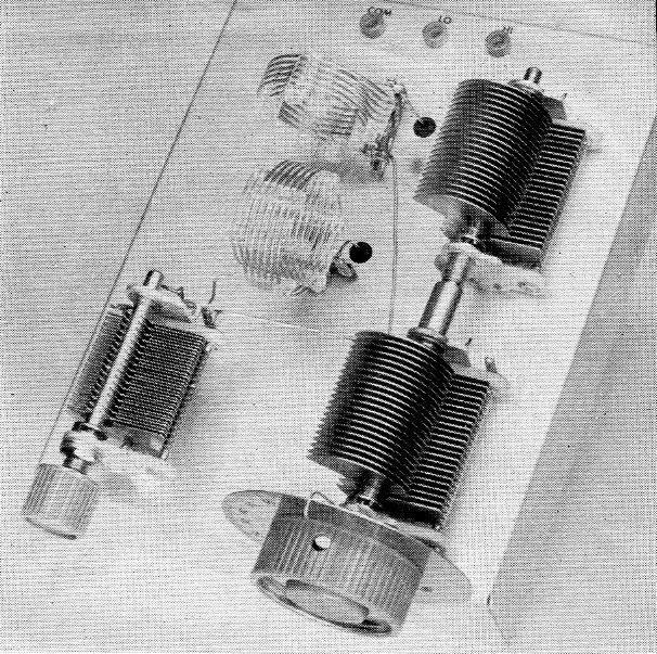
The five-band coupler used with the antenna. The L1L2 assembly is toward the rear of the aluminum chassis. L3L4 is in front of it, mounted so the coupling between the two sets of coils is minimized. Pin jacks at the rear are for making connections to open-wire line.
What it is
The antenna is 60 feet long - approximately a 40-meter half wave - center fed. One half of the antenna is vertical, the other half horizontal. Open-wire line is used to feed the antenna, the line being coupled to the transmitter via a multiband antenna coupler. The coupler serves the dual purpose of coupling the transmission line to the antenna and reducing undesired harmonic energy fed to the antenna. Fig. 1 is a drawing of the entire system.
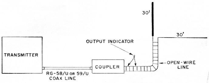
Fig. 1. This drawing shows the setup of the transmitter and antenna system.
The vertical portion of the antenna consists of three 10 foot TV mast sections. These mast sections are available from any radio-parts distributor and cost about two dollars per section. Either aluminum or steel sections can be used, although the aluminum is preferred as it is easier to handle. The masts are usually 1¼ inch in diameter and have one end swaged so they can be fitted together. Incidentally, with suitable guying these mast sections also make excellent low-cost poles for supporting horizontal antennas.
In addition to the mast sections you'll need about 200 feet of plastic clothes line for guying the vertical portion of the antenna. The actual length required will, of course, depend on the installation but 200 feet is adequate, in any event. The vertical should be guyed about 12 feet from the bottom and a few feet from the top.
If the antenna is to be installed on a roof you'll need three guy anchors. In our test setup three screw-in type clothes-line hooks were used to secure the guys. However, should you decide to mount the vertical in your yard, the guys can be anchored to posts or stakes driven in the ground.
The base of the vertical must be insulated, and a soda bottle works out just fine for this purpose. The diameter of the mast section is large enough to slide over the bottle neck. You'll need some form of base to hold the bottle steady. However, as most of the antenna thrust is in the downward direction, which tends to hold the bottle steady, a block of wood with raised sides, Fig. 2B, will do.
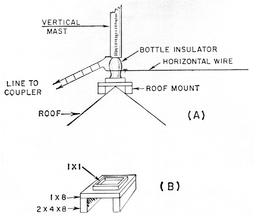
Fig. 2. Details for mounting the antenna are shown at A At B is one method for constructing a mounting base.
The horizontal portion of the antenna consists of a 30 foot length of antenna wire. One end is wound around the bottle, Fig. 2A, and the other should go to a strain insulator which can be supported by a guy line to any convenient anchorage.
TV open-wire line is used for the transmission line. The length of the line will, of course, depend on your installation. You may find it inconvenient to come through the wall or window of your shack with the open-wire line. If so, you can run the line to the nearest entrance to the shack and secure the line with a stand-off insulator, and then come into the shack with 300 ohm twin-lead.
Making the installation
If you decide to install the vertical in the yard or away from the house it is a good idea to get the base of the antenna at least eight feet above the ground. This will get the feeder high enough so there won't be any danger of decapitating the XYL when she's hanging out the family wash (also, it should be too high to be used for a clothes line!). A 4 × 4 post 10 feet long should work out well as a mount for the vertical.
Fig. 2 shows one method of making a simple base mount if the antenna is to be mounted on a peaked roof. The mount consists of two eight-inch lengths of 2 × 4 and a piece of one-inch lumber. The width of the one-inch stock will depend on the pitch of the roof. As can be seen in the drawing, the edges of the 2 × 4s rest on the roof slope and the one-inch stock is on the roof peak. When the vertical is mounted in place there is enough downward thrust to keep the block from creeping.
The guys can be attached to the mast by simply drilling holes in the mast, the holes being large enough to pass the plastic clothes line, and tying the line directly to the mast. Lay the vertical on the ground and measure off the length of the guys, which will, of course, depend on the anchor points. Also, drill a hole about % inch from the bottom of the mast and install a nut and screw. The head of the screw should be mounted inside the pipe with the threaded portion extending out. Use a lock washer and tighten up the nut. When you mount the vertical on the soda bottle it will be a simple matter to fasten one feed wire over the screw, using another nut to hold the end of the line to the vertical.
Before mounting the vertical, put a cork in the soda bottle: otherwise it is likely to fill up with water coming down the pipe. You can, of course, plug up the top of the vertical, but this isn't necessary. Any water coming down the pipe will escape around the bottle.
After the vertical is mounted in place and guyed, you can install the horizontal wire. Wrap one end of the wire around the bottle and secure the other end to a guy point, using an insulator at the end of the 30-foot length. If you don't have enough room to stretch out the wire straight, it can be run in an L or U shape. Try to avoid running the wire close to rain gutters or pipes. Also, the wire doesn't have to be horizontal; it can slope downward to a guy point if desired.
One side of the feeder goes to the base of the vertical and the other side to the horizontal wire. Don't worry about the length of line to the shack as it isn't critical. It can be as short as five feet or as long as required to reach the shack. (Well, that seems reasonable! - Ed.)
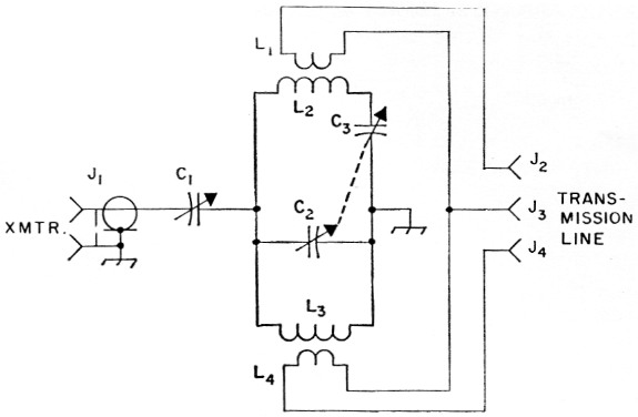
Fig. 3. Circuit diagram of the multiband antenna coupler.
| C1 | 250 pF variable capacitor (Hammarlund MC-250-M). |
| C2,C3 | 325 pF variable capacitor (Hammarlund MC-325-M). |
| J1 | Coax chassis receptable, SO-239. |
| J2,J3,J4 | Tip jacks. |
| L1 | 1.6 µH, 5 turns No. 18, 1¼ inch diam., 10 turns per inch, mounted inside L2 (Illumitronic Air Dux 1010). |
| L2 | 1.1 µH, 5 turns No. 14, 1¾ inch diam., 10 turns per inch (Illumitronic Air Dux 1410). |
| L3 | 3.2 µH, 10 turns No. 18, 1¼ inch diam., 10 turns per inch, mounted inside L4 (Illumitronic Air Dux 1010). |
| L4 | 2.1 µH, 6 turns No. 14, 1¾ inch diam., 10 turns per inch (Illumitronic Air Dux 1410). |
The antenna coupler
The antenna coupler circuit shown in Fig. 3 is a multiband type that covers 80 through 10 meters without band switching. Coupling from the transmitter is controlled by C1. Two links are provided, L4 for coupling to the feeder on 80 and 40, and L1 for 20, 15 and 10.
The coupler is built on a 2 × 7 × 9 inch aluminum chassis. Arrangement of the components is not particularly critical but it is a good idea to follow the general layout of the unit shown in the photograph. C1 must be insulated from the chassis, so standoff insulators, ½ × 1 inch (Millen 31001), were used to support the capacitor. Before drilling the holes for mounting C2 and C3, connect them together with a shaft coupler. Set both capacitors at maximum capacitance (plates fully meshed) and tighten up the lock screws on the coupler. With the capacitors coupled together it will be easier to find the correct dimensions for the four screw holes when mounting the capacitors on the chassis.
The four coils are mounted on terminal strips and are supported by their own leads. The three leads from the links to the antenna terminals are run through rubber grommets through the chassis top and back to three tip jacks at the top rear of the chassis.
Adjustment procedure
It is a good idea to set up the coupler with a dummy load first so you can get the "feel" of the tuning. A 60 watt lamp bulb is good for this purpose with Novice-power transmitters. Connect the screw portion of the base to J3 and the base tip to J4. Use a length of 50- or 70-ohm coax line to connect the coupler to the rig. Set your rig for 80 meters and apply power. First, resonate the final amplifier for a dip. Next, tune C1 to about mid-range and then adjust C2C3 for an indication in the lamp load. Once the bulb lights, readjust C1 and then C2C3 again for maximum brilliance of the lamp. You'll probably have to adjust the transmitter amplifier tuning to keep it in resonance as you make the adjustments. Make a note of the capacitor settings and then proceed to the other bands, using the same method of adjustment. When setting up on 20, 15 and 10, change the antenna lead from J4 to J2. The lead to J3 doesn't need to be changed.
The same procedure can be followed with the antenna connected to the coupler. The capacitor settings won't be exactly the same when you connect the antenna but should be fairly close. However, you will need some type of indicating device to show when the coupler is correctly tuned. If you have an s.w.r. bridge it should be installed in the coax line between the two units. The coupler is then adjusted so that a match is indicated on the coax line.
If you don't have an s.w.r. bridge then you can use a dial lamp as an output indicator. The dial lamp should be connected across a portion of one of the feeders. The method for doing this is shown in Fig. 4. Use two lengths of wire about two feet long. Clip the leads to one of the feeders, placing the clips about a foot apart. Adjust the coupler so that the dial lamp lights up. Keep one thing in mind in making this adjustment: for any one distance between clips, the brighter the light, the more power there is going up the feeders to the antenna. If the bulb should get too bright, reduce the separation of the clips on the feeder wire. This will reduce the pickup from the line.
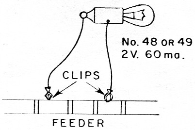
Fig. 4. Dial-lamp output indicator.
This coupler was tested with a rig running 100 watts input. This is also about the maximum power the coupler will handle without the capacitors arcing over from the high r.f. voltages present. Any readers desiring a higher-power version of the coupler can find such a unit described in the 1958 or 1959 editions of the Handbook in the chapter on transmission lines.
Lewis G. McCoy, W1ICP.