The fox vox adapter
Sequenced transmitter receiver change over system.
By proper sequencing of the operation of transmitter-power and antenna relays, arcing at the antenna relay is avoided. As a result, small inexpensive relays may be used even with a high-power transmitter.
For several years I have been using a unique, rather complex transmitter-receiver control device for operation of my s.s.b. equipment. This device was noiseless and did the changeover extremely rapidly. In performance tests, using the "tick" from WWV to actuate the voice control to the s.s.b. exciter, and a receiver to demodulate the s.s.b. exciter output, all 5 cycles of the 1000 c.p.s. wave which compose the "tick" were registered on a scope connected to the receiver output.
Electronic t.r. systems
Despite the noiseless and rapid performance of this circuit, it lacked one feature necessary for satisfactory voice break-in operation. It did not provide for t.r. operation of the transmitting antenna. Many operators would have been satisfied with the operation of an electron-type t.r. device in this assignment. But the manner in which such devices are used makes the arrangement prone to unpredictable performance with regard to signal loss suffered when QSYing the receiver within a given band, with random final-amplifier tuning adjustments.(1) If one wants the best signal to receiver-noise ratio, it seems that the only really satisfactory antenna t.r. device to date is the old metallic-contact gadget, the s.p.d.t. relay.
Relay change-over
On-the-air listening to various s.s.b. signals showed that most relay-operated voice-control systems perform with no noticeable clipping of the first syllable. However, there seems to have been little concern by designers about the timing precision desirable in the sequence of operation of the relays used to control the receiver, change over the antenna, and control the transmitter. Inattention to the relay-sequence problem can result in quite fat arcs at the antenna relay contacts from time to time.
Improving the relay system
An adapter which will provide improved performance of the usual relay-type voice-control system has been developed and used for several months. It uses three carefully-sequenced relays for receiver control, antenna change-over and transmitter control. The inherent operate time of these relays, in conjunction with their associated time-control components, functions to cause them to operate so that only one relay is in process of change-over at a time. In other words, each relay waits until the preceding one has completed its function. The circuit is beautiful in its precision and electron-tubeless simplicity. The order of operation from listen to transmit is:
- Turn off receiver.
- Change antenna from receiver to transmitter.
- Turn on transmitter.
From transmit to receive, the reverse sequence of events takes place. This is not the order of operation usually obtained when one relay is used to control one or more additional relays.
Causes of arcing
In the conventional arrangement where relays are operated in tandem, the operator may wonder why he still gets arcs and contact burning at the antenna relay even though he may have interlocked the contacts and done some contact bending in an effort to get the sequence of operation correct. The trouble he is experiencing may be due to antenna relay-contact bounce on make. The antenna change-over contact has simply not stopped bouncing before the transmitter starts delivering r.f. energy to the still-bouncing relay contact. The proposed arrangement takes this contact bounce time into account and delays r.f. output from the transmitter until contact is firmly established between the transmitter and antenna.
Antenna relays
One advantage of a properly-sequenced control-relay arrangement is the ability to use almost any small relay to do the antenna change-over job. Since the antenna change-over contacts do not switch under power, almost any but the frailest relay contacts will handle full amateur power, if the r.f. switching is done at a low-impedance point as it usually is. The principal restriction on relay selection is that the dielectric on which the relay contacts are mounted be able to withstand the applied r.f. voltage. This requirement is not one of arc-over but that of dielectric heating caused by high-frequency currents. Dielectric heating from the r.f. current can cause insulation breakdown where the same d.c. or 60-cycle voltage would cause no trouble. In particular, relays which have the movable contact connected to the relay frame are susceptible to dielectric heating. This construction promotes heating of the relay coil due to the effect of r.f. current flowing from the core piece of the coil through the coil insulation to the coil winding.
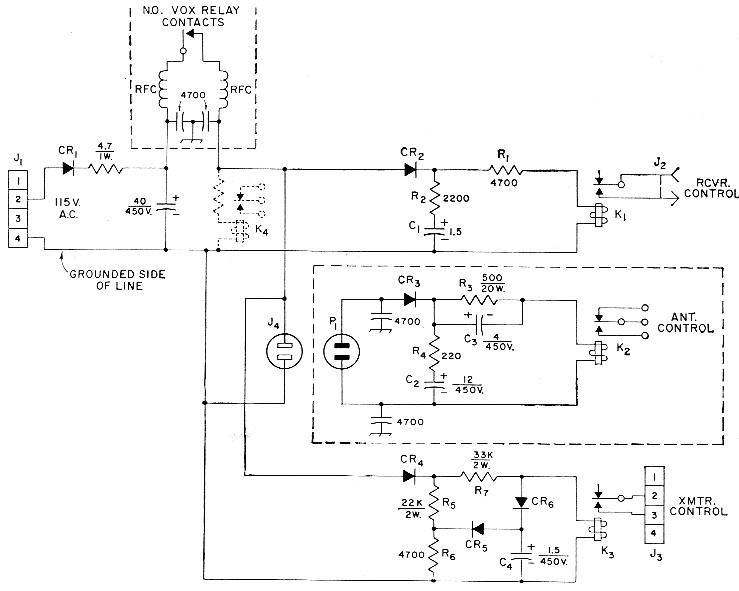
Fig. 1. Diagram of the sequenced control circuit. Resistances are in ohms. Capacitors marked with polarity are electrolytic and capacitances are in ;rf. (see text in regard to Cs and C4); others may be paper or ceramic and values are in pF. Resistors are 10 per cent ½ watt unless irdicated otherwise. Antenna-control portion (shown within dashed lines) should be installed at the transmitter. Note: pin 4 of J1 must go to grounded side of line.
| C1-C4 inc. | 450 volt electrolytic (see text). |
| CR1-CR6, inc. | Silicon diode: 360 p.i.v., 200 mA (SarkesTarzian K-200). |
| J1 | Chassis-mounting 4-prong male connector (or other connector whose connections may be polarized) (Cinch-Jones P-304-AB). |
| J2 | Phono connector. |
| J3 | Chassis-mounting 4-prong female connector (Cinch-Jones S-304-AB). |
| J4 | Miniature polarized chassis-mounting a.c. outlet. |
| K1,K3 | S.p.d.t. relay, 6000 ohm coil (Sigma 11F-6000-G/S11.). |
| K2 | Antenna relay from ARC-5 antenna-tuning unit, or similar (see text). |
| K4 | See text. |
| P1 | Polarized a.c. plug. |
| R1-R7 inc. | See text. |
Two very commonly-available relays have been satisfactorily used as antenna change-over relays in a sequenced control system. Either one will handle any legal amateur power into the usual coaxial cable. My favorite of the two is a little gem which I have wanted to put to work for some time. It is the relay from the BC-442 antenna tuning unit of the ARC-5 and SCR-274 series. There must be thousands of these little beauties which have been relegated to the attic by amateurs who bought tuning units to get the vacuum capacitor and thermocouple meter. They are still available on the surplus market at a reasonable price. This relay is beautifully insulated for high r.f. voltage. It has a set of s.p.d.t. contacts for r.f. switching and a set of normally-open control contacts, one contact of which is at relay-f rame potential. The coil of this relay is designed for 24/28-volt d.c. operation. The other relay which has been proven in the antenna changeover circuit is a commonly-available surplus d.p.d.t. relay. Some of these also have a set of s.p.d.t. control contacts. Both Advance and Leach have manufactured a relay of this type. The contacts are insulated with ceramic and the coil is intended for 115 volt 60 cycle operation.
These relays will work well from the same d.c supply voltage as the ARC-5 relay, although experimental readjustment of delay values may be necessary.
The relays used for receiver and transmitter control are miniature sensitive relays manufactured by Sigma and cost less than $2.00 each new. They operate quietly and rapidly.
The circuit of the adapter is shown in Fig. 1. The system is controlled by a pair of normally-open contacts on the VOX relay. K1 is for receiver muting, K2 for antenna change-over and K3 for transmitter power control. The contacts of K1 and K3 may be used in any desired manner to suit the individual control arrangement, since the adapter system provides proper sequencing, including allowance for bounce, in both directions of the armature travel. However, the relays of the adapter should not be used to control other relays; they should perform the intended function directly to preserve the desired sequencing. This sequencing is illustrated graphically in Fig. 2. Fig. 2A shows the progression in changing over from the receiving condition to the transmitting condition, while Fig. 2B shows the reverse progression in returning to the receiving condition.
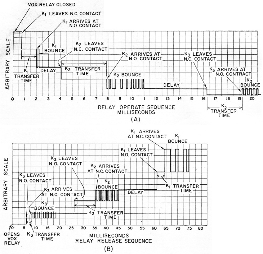
Fig. 2. Graph showing relay sequencing, including relay "bounce" characteristics. A shows the characteristics on "operate" (relays energized), while B follows the sequence on "release" (relays deenergized).
No specific circuitry is shown for receiver and transmitter controls, since this will depend upon the equipment in use and the operator's preference. As suggestions, the receiver-control contacts may be used to raise the cathodes of the r.f. and i.f. stages far enough above ground to disable the receiver, or they can supply the required cutoff negative voltage to the a.v.c. line. The transmitter-control contacts may be used to open cathode circuits on stand-by. In cases where additional transmitter-control contacts are desired to provide a cutoff bias to the final amplifier for tube protection or shot-noise quieting, an additional relay, K4, may be used without delay and connected as shown in dotted lines.
Delay circuits
As previously stated, in going from receive to transmit, K1 should close first and as quickly as possible to disable the receiver. When the normally-open contacts of the VOX relay close, approximately 140 volt is applied to K1 through R1 which serves to limit the power dissipated by the coil to a safe level. Capacitor C1 produces an insignificant delay in the closing of K1, since the series resistance common to C1 and K1 is negligible. The resistor R1 tends to speed up the action of K1.(2)
K2 must wait for K1 to close and for contact bounce to subside. This necessary delay is an inherent characteristic of the relays recommended for K2. Therefore no components are needed to delay the operate time of K2. R3 limits the power dissipated by the coil of K2. R3 and C3 in series with the coil of K2 actually act to make the relay operate faster than it would if 24 volts was applied directly to its coil. Nevertheless, the resultant delay is adequate if the suggested relays are used. Again, C2 has an insignificant effect on the operate time of K2 both because of the negligible common series resistance.
K3 is inherently fast-acting, so its action must be delayed to permit K1 and K2 to operate first. This delay is supplied by C4 and the common series resistance of R7. These latter are the only components affecting the operate time of K2 since, on the receive-to-transmit cycle, the voltage divider R5-R6 biases CR5 to nonconduction to prevent R6 from affecting the time delay, although CR6 will conduct. We now have all relays energized with the receiver off and the transmitter on.
From transmit to receive
To go from transmit to receive, we first must turn off the transmitter. To do this as quickly as possible after the VOX relay opens, we should open the K3 coil circuit. This is done quite effectively by CR6 which electronically disconnects C4 from K3. (CR6 is so polarized that it will not conduct in the direction of the discharge current from C4.) CR5 is now no longer back-biased, so that C4 is rapidly discharged through R6. (Discharge of C4 is necessary, of course, so that C4 will be ready to provide an accurate delay on the next receive-to-transmit cycle.)
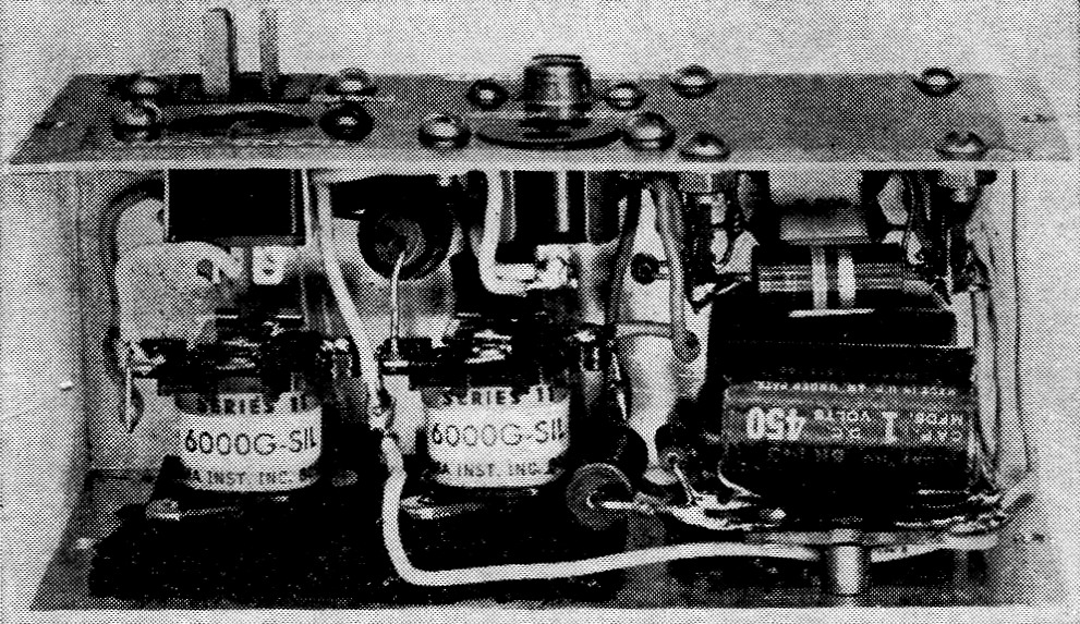
This unit includes K1 (center) and K3 (left). The components are assembled in a 2¼ × 2¼ × 5 inch aluminum Minibox. Note the sponge-rubber relay mounting.
The release of K2 is delayed by the charge on C2, and K1 is delayed on release by the charge on C1. CR2, CR3, and CR4 are isolators to prevent interaction between the timing circuits.
Receiver noise suppression
The r.f. chokes at the VOX relay contacts are used to suppress electrical noise generated by the small arc as the contacts open. Since the receiver is still sensitive for a few milliseconds after the VOX relay operates, any r.f. disturbance of this sort can be picked up by the receiver unless the shielding is very complete in the antenna circuit. The chokes may be omitted and added later if found to be required. In most instances, however, they will be found to be beneficial. They should be installed at the VOX relay contacts with the shortest possible leads between the chokes and the relay contacts.
The installation of chokes in the receiver-control contacts of K1 may also prove desirable. Even the low current switched by these contacts can cause an r.f. disturbance which can be picked up by the receiver in some instances. While not shown in the schematic of Fig. 1, these chokes can be seen in the photograph of the adapter unit.
Capacitors
Electrolytic capacitors are used because of the size problem which paper capacitors would present. Electrolytic capacitors have proven to be entirely satisfactory in this low-impedance application. Because of the manufacturing tolerance associated with the relays and capacitors, it may be necessary to determine experimentally the value of capacitance to provide the correct timing. The final proof of performance of this gadget is its ability to operate without antenna arcing or "pops" in the receiver. The tolerance on electrolytics is none too good, of course, and in the case of the 1.5 µF capacitors, C1 and C4, it will he necessary to make a selection from a group of 1 and 2 µF units. For this reason, it may he more practical to use tubular paper capacitors in these two positions, if space can be found for them. The desired capacitance can be made up of a 1 µF unit in parallel with a 0.5 µF capacitor.
Relay characteristics
The operate times shown in Fig. 2 are representative of what can be done with the relays used. The over-all design is pretty well dictated by the characteristics of K2 in this instance, since it is inherently slower-acting than K1 or K3.
The total timing period of the release sequence of Fig. 2B is not particularly critical. As shown, it is faster than the normal release adjustment of most VOX systems. As long as the total release timing period does not cause undesirably long "hang-on" of the VOX, the release sequence of the relays can fit into this period in any manner which keeps them from coinciding in operate time. The circuit shown will follow c.w. up to about 15-20 w.p.m. and can be adapted for phonec.w. operation by means of some additional switching.
It should be emphasized that the operating characteristics of no two relays, even of the same make and model, are identical, and that some adjustment of the delay-circuit values given should be expected. An article to follow will describe a method of accurately timing relay operation.
Reducing ARC-5 relay bounce
The very desirable mechanical construction of the ARC-5 antenna relay, which gives it the large contact spacing so desirable for high r.f.-voltage use, brings about a problem in contact bounce. The long springlike contact of this relay is very prone to bouncing on release as the movable contact meets the normally-closed contact.
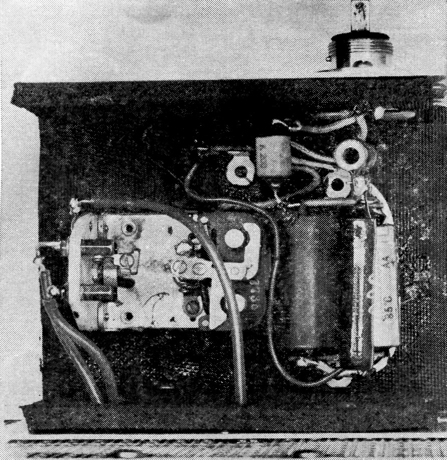
The antenna relay, K2, and associated delay components are mounted in a 4 × 5 × 3 inch Minibox fastened to the rear of the transmitter. The box is lined with sound-deadening material.
A group of four of these relays was checked for contact bounce. The bounce of the movable contact when it reached the normally-open contact was not abnormal, but all four relays showed 35-40 milliseconds bounce time on release when the movable contact arrived at the normally-closed contact. One other ARC-5 relay had a piece of felt inserted between the turns of the springlike movable contact. Tests on this relay showed less than 10-15 milliseconds bounce time on release. Installing a similar piece of felt in each of the four relays showed that bounce time could be cut to less than 20 milliseconds on all relays.
Fig. 3 is a sketch of how the felt was inserted in the contact mounting. The felt is material which can be taken from underneath the cover flaps of the ARC-5 transmitter series and is about 1/16 inch thick. A piece about 3/16 by ¼ inch is used.
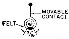
Fig. 3-Sketch showing method of damping bounce in ARC-5 antenna relays.
The graphs of Fig. 2 were taken with the felt installed. If no felt were used, C1 of Fig. 1 would have to be larger to delay K1 enough on release to allow for the larger bounce time of K2.
Acoustical noise reduction
The ever-present noise of relay operation has been a subject of discussion for years. Nothing new is advanced here toward solving this problem. Its existence is, however, acknowledged. The small Sigma receiver- and transmitter-control relays are mounted on sponge rubber to reduce their operational noise. This rubber serves another important purpose. The movable contacts of these relays are connected to the relay frame, so that it is necessary to insulate the relays electrically. The sponge rubber does both the job of mechanical isolation and electrical insulation. Rubber cement of the type used to cement automobile weatherstripping does the job of cementing the sponge rubber to the chassis and the relay to the sponge rubber. The sponge rubber can be seen in the photograph of the adapter unit.
The antenna relay is much the noisiest of the three. It is mounted at the final amplifier in a Minibox which is lined with sponge rubber. The relay is cemented to the rubber without using any mounting screws which would conduct sound to the box.
These noise-reduction techniques are about 50 per cent effective. Enclosing each of the two chassis inside another rubber- or acoustic-tilelined box is an idea for further experimentation.
Keying filter
The graphs of Fig. 2 show that K3, the transmitter-control relay, bounces quite a bit when the movable contact makes with either the normally-open or normally-closed contact. Ii this relay is used to key a transmitter for c.w. operation, clicks can result if a keying filter is not used. The usual c.w. click filter, which should be a normal required transmitter accessory, will take care of any tendency of the bounce to cause clicks.
Notes
- Campbell, " Variations in tr switch performance," QST, May, 1956.
- See Stein, "Some hints on relay operation," QST, June, 1956.
Grady B. Fox, Jr., W2VVC.