A v.h.f. variable-frequency crystal exciter
Adapting the vxo principle for v.h.f. use.
Variable-frequency operation on the v.h.f. bands, with stability comparable to lower frequencies, is the goal of the serious v.h.f. man. Most v.f.o.s are low-frequency oscillators followed by stages multiplying to the desired v.h.f. band. With great care in construction and a bit of luck, an acceptable sounding signal may be realized, but really T9 signals on 144 Mc are usually only a fond dream.
A QST article on a variable crystal oscillator circuit using inductance to lower the series-resonant frequency of the crystal(1) sounded like the answer to the v.h.f. man's problem. A test circuit was hurriedly put together using the basic variable crystal oscillator as described by W3BWK. The results were encouraging; a good crystal-sounding signal ow 144 Mc. with plenty of frequency swing per crystal and excellent reset accuracy.
Considerable thought was given to the eventual application of the basic VXO circuit. The widespread use of 8 Mc crystals in v.h.f. transmitters dictated the use of this type of crystal in the exciter. Subsequent investigation proved that 8 Mc fundamental crystals can be swung in frequency sufficiently to provide up to 500 kc at 144 Mc, depending on the crystal activity and the manufacturing process used in finishing the crystal. In general, any surplus crystal plugged into this exciter will permit a swing of 100 to 500 kc at the operating frequency.
Rebuilding and debugging yielded a basic variable-frequency crystal exciter that is simple in circuitry, easy to build and stable enough to be used for single sideband. Since no heterodyning action is involved there is no spurious beat problem. The oscillator runs continuously, and at low power level, avoiding the drift so often observed at the start of each transmission in v.h.f. work. Though the exciter was intended primarily for 144 Mc use at W3KXI, frequencies for 50 and 220 Mc operation are readily obtainable. Frequency swings up to one megacycle at 144 Mc are obtainable with specially-processed crystals.
Circuit
The VXO oscillator circuit is shown in Fig. 1. The inductance, L1, is used to lower the series-resonant frequency of the crystal. The dual-section capacitor, C1, lowers the oscillation frequency as the capacitance is increased.
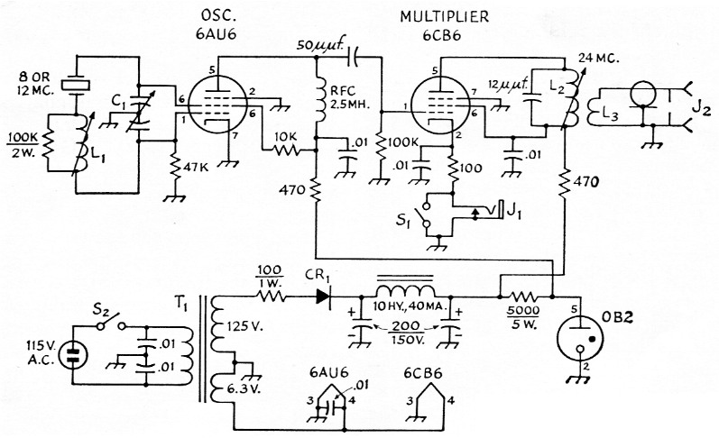
Fig. 1. Schematic diagram and parts information for the v.h.f. VXO. Capacitor values in µF unless specified. Those marked with polarity are electrolytic; others mica or ceramic. Resistors ½ watt unless specified.
| C1 | 50 pF per section split-stator (Hammarlund HFD50). |
| CR1 | 150 mA silicon rectifier. |
| J1 | Closed-circuit jack. |
| J2 | Coaxial fitting. |
| L1 | No. 26 enam. close-wound on ½ inch form with h.f. iron slug, winding length 1 inch (CTc PL57 form, with 20063-K core). |
| L2 | 22 turns No. 26 enam., close-wound on ¼ inch form with v.h.f. iron slug (CTc PLS6 form with 20063-0 core). |
| L3 | 3 turns insulated hookup wire over B-plus end of L2. |
| S1,S2 | Toggle switch. |
| T1 | Power transformer, 125 V 40 mA, and 6.3 V 0.6 A or more. |
The crystal can be a fundamental 8 or 12 Mc cut, or overtone-type (third or fifth overtone) operated on the fundamental frequency. For maximum frequency swing, with high stability, special VXO crystals or fifth-overtone types are preferred. The second stage is a frequency multiplier to 24 Mc.
A word about components: the critical part of the VXO circuits is the coil, L1. In line with good v.f.o. practice, the coil form should be of ceramic material with secure locking action of the tuning slug. The Q should be as high as possible. The tuning slug should be chosen for the frequency of operation, to realize the maximum Q from the coil. Capacitor Ci can be any good dual-section model of the specified capacitance and plate shape. All other components are noncritical and standard.
Regulation of the plate and screen voltage for the oscillator is a must. The keying jack is included for amplifier disabling during receive periods. Diode frequency multiplication through a hot transmitter with plate voltages off can put a good S9 signal on 144 Mc. This may be good for frequency spotting but difficult for receiving; hence the keying jack and spotting switch.
The power supply is shown for convenience only. To reduce the ripple component in the d.c. output, full-wave rectification is recommended. I used half-wave rectification to suit the power transformer available, but note the large amount of capacitance needed to reduce the ripple to a suitable level.
If the power supply is to he constructed on the same chassis as the exciter, use of the silicon rectifier is recommended from the standpoint of reduced temperature rise. If possible, all heat-producing components should be located on the outside of the chassis. Excessive temperature rise in the box will have an adverse effect on the coil stability. For the more technically inclined reader, the careful study of the articles by W3BWK on the theory behind the VXO principle is recommended.
Construction
A 3 × 5 × 6 inch aluminum chassis houses the exciter. The placement of the coil, capacitor and crystal socket should be such as to give the shortest lead length. If its limited frequency coverage will suffice, the crystal can be soldered permanently into the circuit, eliminating the shunting effect of the crystal holder. This will increase crystal activity and frequency swing.
The dial calibration linearity depends on the crystal activity with maximum plate and grid capacitance in the circuit. The more active the crystal, the less is the effect of the increase in capacitance across the plate and grid on the frequency variation; i.e., less crowding at the low frequency end of the dial.
The series coil, L1, was chosen to vary over a large inductance range in order to accommodate crystals in the 8 to 12 Mc range. If 12 Mc crystals only are used, larger diameter wire can be used for the coil, reducing the number of turns required and improving the temperature stability and Q. In any event, the coil should be wound with the wire under tension, with no cement applied to hold the wire in position. Inductance requirements will vary with the crystal type and circuit layout. A good rule to follow in arriving at the best coil for the particular circuit is to use the least amount of wire necessary to cover the range desired. Use the slug for maximum inductance and Q. A good sturdy coil form is required for this service.
The remainder of the exciter is conventional, with placement of components and wiring in line with good v.f.o. practice. The output circuit can be varied to suit the transmitter with which the exciter is to be used. Recommended circuits are suggested in the Handbook.
If the exciter is to be used in conjunction with a high-power transmitter, thorough shielding and filtering of the exciter are recommended for best results. This should include bottom plate, tube shields and even a crystal shield, if a plug-in crystal is used, and power-line filtering that will be effective at transmitter frequency. Excessive r.f. in the exciter can produce weird results.
Adjustment
A grid-dip meter is needed for the initial adjustments of the tuned circuits. With the crystal plugged into the circuit and C1 set at maximum capacitance, check L1 for resonance near the frequency of the crystal in the circuit. Resonance should be approached from the high-frequency side, removing coil turns so that resonance is reached with the tuning slug into the coil about three quarters of the way. Next, resonate L2, to 24 Mc, with the exciter output feeding the v.h.f. transmitter. This completes the preliminary circuit adjustments.
Crystals should be selected on the basis of the highest frequencies to be covered. Example: To cover from 144 to 145 Mc, select a crystal frequency of 145 / 12 = 12.08 Mc, and add .01 Mc to allow for overlap and crystal variations. If a continuous calibration is desired, similar crystal types should be used.
Final adjustments as follows:
Turn the slug of L1 to the minimum inductance position and plug in the crystal. Set C1 to minimum capacitance.
Apply power to the exciter and check the crystal for oscillation near the calculated frequency, checking the frequency with the station receiver, preferably on the crystal fundamental.
Set C1 to maximum and note the frequency change.
With C1 at maximum, turn the slug into L1 to lower the frequency, checking with the receiver until the lowest desired frequency is reached.
Check tuning range by rotating C1 to minimum setting, and touch up the L1 slug if the tuning range is not correct.
Calibrate the dial for each crystal used.
Using the receiver S meter, peak L2 for maximum output.
Tuning range of 1 Mc or greater can be obtained on 144 Mc by the use of special crystals. However, for s.s.b. or other high-stability re-
(Continued on page 148)
Notes
Henry J. Saborsky, W3KXI.