Transistor preamplifier for dynamic microphones
Self-contained unit of small dimensions.
The rugged character of dynamic microphones makes them well suited to ham use. Their relatively low output, however, usually makes necessary the use of amplification greater than that available in many manufactured and home-built audio sections. The preamplifier described here is a small self-contained unit that may be plugged in between the microphone and the microphone jack of an existing rig.
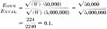
The great popularity of the high-impedance, high-output-level microphone, as represented by the crystal and ceramic types, has led the great majority of amateur transmitter builders both commercial and home-brew - to design rigs adapted to their use. Sooner or later, however, many wish to use the dynamic microphone, well known for its rugged-service record in the face of extremes of temperature and shock. These units are now available in high-impedance models having a frequency response more than adequate for communication service, and at reasonable prices. However, the output specifications of these units may be misleading. If, for example, both a high-impedance dynamic microphone and a crystal microphone have rated -55 dB output, the power outputs are equal but the voltage outputs are vastly different. Since E = 1/ WR and W is the same for each type then, assuming typical impedances,
![]()
The output ratio is then
It is no wonder, then, that by connecting the high-impedance dynamic microphone to the normal crystal-microphone input channel, low modulation is the result. In the writer's experience, the increased sound level required at the microphone is greater than the vocal cords can deliver. Increased amplification is required but it may not always be possible, or at least desirable, to add the necessary components internally in the rig. The preamplifier to be described is contained in a small external package, complete with battery power supply.
Circuitry
To keep the unit small and simple, a transistorized circuit is used. To provide a match for the 50,000 ohm impedance of the microphone, the first stage is an emitter follower. This type of transistor amplifier is similar to a tube cathode follower in that it has a high input impedance and a low output impedance. The output of this stage is well suited to driving the second stage which is a common-emitter amplifier. The output impedance of the second stage is approximately 1500 ohms, which reduces hum pickup problems.
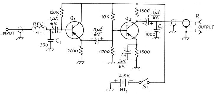
Fig. 1. Circuit diagram of the transistor preamplifier. Unless indicated otherwise, capacitances are in pF; C1 and C2 are mica; other capacitors are subminiature electrolytic. Resistances are in ohms and resistors are ½ watt.
| BT1 | See text. |
| Q1,Q2 | See text. |
| P1 | Microphone plug. |
| S1 | S.p.s.t. slide switch. |
R.F. filtering
Since most antenna systems are not accurately balanced, some r.f. is usually floating around the shack. Any small amount of r.f. getting into the preamplifier cables will be rectified by diode action in one of the transistors and cause feedback. The input filter consisting of the r.f. choke and C1, and the output filter C2 reduce this possibility. Due to the low amplifier impedances, the capacitors will not impair the audio response.
Power supply
Each stage is biased to provide stable operation over a reasonable temperature and battery-voltage range. The total battery drain is approximately 2 mA, giving essentially shelf-life service from the three Z-size pen cells - even for rag-chewing specialists. The switch should he left "off", however, when the station is not in use.
Transistors
The unit shown in the photos uses a transistor made by General Transistor, similar to their type GT-81. This transistor is a p-n-p germanium type and is typical of many available inexpensive "entertainment"-type transistors. The transistors that may be used in this circuit are too numerous to be listed here; however, a few are: the Texas Instrument 2N369, Raytheon 2N362, RCA 2N408, and GE 2N191. Select one having a nominal beta or hfe between 50 and 100. Circuit changes should not be necessary with any transistor of this general type. N-p-n transistors will work as well, but it will be necessary to change all capacitor polarities and reverse the battery supply. Any of the above transistors will cost approximately $1.50.
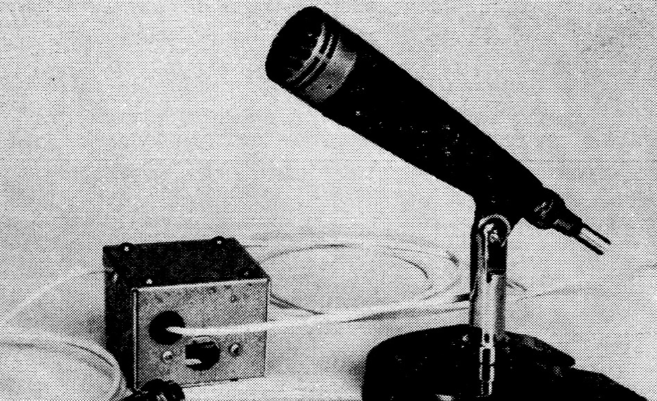
This complete self-powered two-stage preamplifier is hardly noticeable alongside the dynamic microphone with which it is used.
Construction
The amplifier and battery supply are housed in a 2¼ × 2¼ × 1¾ inch aluminum box. All amplifier components are mounted on a plastic board that is raised on spacers. Components are located on both sides of the board for convenience. Transistor sockets were used, but are not considered necessary. The transistor leads may be soldered directly, provided that care is taken not to allow the heat to damage the transistor. Keep leads ½ inch long and use a heat clamp during soldering. Component placement is not critical but the input and output r.f. filters should be located as near to the shielded input and output cables as possible. The battery holder is a standard item available at radio and hobby supply houses. Other batteries may be used, including the long-life mercury type. None of the component types is critical and any manufacturers' items may be used for the listed components. Both the input and output cables may be as long as desired, allowing the preamplifier to be located in any convenient position.
Operation
Before placing the preamplifier in system operation, it is a good idea to check the voltages at each transistor emitter. Approximately 2 volt should appear at the emitter of Q1 and 1.5 volt at the emitter of Q2. These voltages may vary by 50 per cent and still be normal. The characteristics of transistors vary more widely than those of vacuum tubes. About 40 dB of gain will be obtained from the preamplifier, so you can use that dynamic microphone without shouting into the next district. Mobile fans may find the preamplifier handy when substituting a dynamic microphone for a carbon unit.
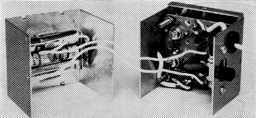
Exploded view of the transistor preamplifier. Most of the components are mounted on the two sides of a perforated fiber or Formica sheet. The Penlight cells are mounted in the cover of the box which is approximately a 2 inch cube.
Robert F. Witters, K6VGA.