Measuring coil Q
Good results with simple test gear.
Most everyone knows the importance of Q in r.f. circuitry, but few realize it can be measured without expensive laboratory equipment. W7LHZ's method requires only a grid-dip oscillator and an antenna impedance bridge for reasonably accurate measurements up to 50 Mc.
One can't get very far in r.f. circuit work without running into the subject of Q. As the books all say, Q stands for quality the quality of a coil or capacitor - and that can be just as important as the amount of L or C involved. In general, the higher the Qs of the reactive elements, the better will be the performance of a circuit. Capacitors have high Q built into them, at least up through the h.f. range, but the kind of coil chosen and the way it is made have a lot to do with the losses there. What is needed is a simple way to measure coil Q, and this article will show how to do it without the usual expensive test equipment. Continue reading for a better idea of what Q is, or skip down to the subhead if what you want is the method.
To review briefly, a resistor may appear to be just a resistor to d.c., a.f., and low r.f. currents, but coils and capacitors don't behave so nicely - they don't act like pure reactances. Coils have d.c. resistance and a different a.c. resistance as well as their inductive reactance. Capacitors have a.c. resistance, too, besides their capacitive reactance. The figure of merit, Q, was devised to relate these properties and equals the reactance divided by the resistance. It is a ratio without sign, since the sign of the reactance is not used. The resistance and the inductance must be taken at the operating frequency if any of the materials used in construction are frequency sensitive.
For example, a coil rated at 7 microhenrys inductance has about 300 ohms reactance at 7 Mc. This can be found from the reactance charts in the Handbook or by multiplying the inductance by 2rrf. If the coil had an a.c. resistance of 10 ohms at this frequency, its Q would be 300 divided by 10, or 30. The lower the a.c. resistance compared to the reactance, the higher the Q and the better the coil will be for most applications.
Commercial Q meters use a basic circuit similar to Fig. 1 for measuring Q. A small r.f. voltage, Eg, is applied to a series-resonant circuit consisting of L, the coil being tested, and C, a built-in capacitor. Rc, the r.f. resistance of the capacitor, is negligible compared with RL, the coil resistance we are interested in, so the latter is what limits the current at resonance. Eg and Es, the voltage drop across the reactance of the capacitor (same as that across the coil), are measured, and their ratio, Es/Eg equals the coil Q.
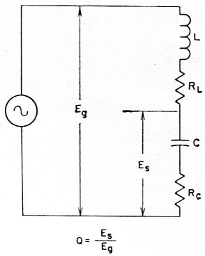
Fig. 1. Basic circuit used in a commercial Q meter. RL is the r.f. resistance of L, the coil under test; RL is the resistance of the Q meter capacitor, C.
This sounds simple, but there are a few things that make it difficult to obtain accuracy with such a hookup on the experimenter's bench. Input voltage Eg may be too low to measure with the usual diode r.f. probes, and the circuit would be detuned considerably if such a probe were used to measure E. At the same time, if a grid-dip meter were used for the generator, voltage regulation would be so poor that moving the probe from one position to another would change the voltage as well as the frequency. Therefore, this type of Q measurement had best be made with a factory-designed and calibrated meter.
Using simple equipment
Fortunately, there is an easy way out for the ham. Since the value of r.f. resistance is what is wanted, just measure it. How? With an impedance bridge - it is made to measure r. f. resistance. Here's the method: Set up the bridge, feeding it with a grid-dip meter or other low-power source at the operating frequency. Connect the coil to be tested in series with an air-spaced variable capacitor across the "unknown" terminals of the bridge, as in Fig. 2. Adjust the capacitor and the variable element of the bridge until a complete null is obtained. (If a null cannot be found, the variable capacitor will not resonate with the coil or the bridge may not go low enough in resistance.) Take the value of resistance found, and divide it into the reactance of the capacitor to find the actual value of Q.
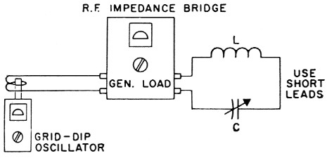
Fig. 2. Setup for measuring r.f. resistance of coil L using grid-dip meter, imaedance bridge and variable capacitor C.
To find the reactance of the capacitor, remove it from the circuit and measure the capacitance in use (being careful not to change the setting). If a capacitance bridge is not available, use a grid-dip meter and a standard coil as described in the Handbook chapter on measurements. The reactance can be found from the Handbook charts or the formula Xc = 1 /2πfC. With air-core coils, Q changes rather slowly with frequency, so a fixed capacitor can also be used and the frequency varied until a null is obtained. The value of resistance found when using a fixed capacitor may be different from that obtained at the same frequency with an air-spaced capacitor. This is because the lower Q of the fixed capacitor adds additional resistance to the circuit. For comparing several coils which resonate at the same frequency with the same capacitance, no calculations need be made - the coil showing the least resistance has the highest Q.
In case you wonder why the reactance of the capacitor instead of the coil is used in these calculations, remember that the two are equal but of opposite sign at resonance, and the sign is not used in determining Q. It is usually easier to measure capacitance than inductance because substitute values are handy and suitable bridges more commonly available. If you know the inductance of the coil being checked, it would be easier, of course, to look up or calculate its reactance rather than to determine the resonating capacitance. It makes no difference which is used - the answer is the same.
For best results, the value of the capacitance used each time, and the frequency, too, should be determined as accurately as possible. If many measurements are to be made, it would be well worth the trouble to calibrate a variable capacitor to show the capacitance for each degree of rotation. If all measurements are to be made at one frequency, the variable capacitor could even be calibrated in reactance instead of capacitance.
Any type of impedance bridge may be used if it works at the frequencies of interest and will indicate resistances between about 1 and 50 ohm. If your bridge was built for antenna work, chances are it will have to be modified to measure lower values of resistance. This can be accomplished easily as follows:
In the variable-voltage-divider type bridge, Fig 3A, the unknown is compared to a standard resistor, R. By substituting a resistor 1/10 the value of R for R, the calibration values are reduced to 1/10 their former value - 50 ohm becomes 5 ohm, 10 ohm becomes 1 ohm, etc.
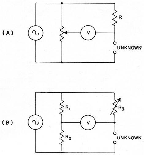
Fig. 3 (A) Basic circuit of variable-voltage-divider-type bridge. In the capacitive divider version of this circuit, a differential capacitor replaces the potentiometer
(B) Basic circuit of equal-arm-type bridge.
In the equal-arm type, Fig. 3B, resistors R1 and R2 form a fixed voltage divider. By reducing R2 to 1/10 its former value, the dial readings of the variable R3 are also reduced by a factor of 10 as above.
Noninductive resistors must be used in these changes, of course. It is not necessary to chop a resistor open to find if it contains wire. Just look at the first band of the color coding. If the first band of color is twice the width of the others, the resistor is wire-wound.(1) If the bands of color are the same width, there is carbon inside.
This same setup will work with all kinds of coils, up to about 50 Mc, where the Q of capacitors becomes significant. It will work with audio filter inductors and teletype toroids as well, if the proper capacitances are used for resonance at the operating frequency. The effect of core materials and shielding can be noted quickly. Just try using core material from a rod-type b.c. antenna at 4 or 5 Mc and see what happens to the Q.
With ordinary ham-shack equipment, plus just a few calculations, a type of measurement that sounds impossible can easily be made with acceptable accuracy.(2) Borrow a capacitance bridge to calibrate a few variables, dust off the antenna bridge, get your g.d.o. back from Friend Jim. and you're in business.
Notes
- This is true of current production, but older wire-wound resistors may not have a double-width band. - Ed.
- One word of warning - be careful about using this method (or any other Q-measuring technique we know of) in cases where the distributed capacitance of the coil is an appreciable fraction of the external capacitance used for tuning. This is true, for instance, of antenna loading coils used at the lower frequencies. The distributed capacitance acts very much as though it were lumped across the coil terminals and causes the coil to have an apparent Q which is lower than the true value. As an example, if the distributed C is 1/10 the tuning C, the true and apparent Qs differ by 9 per cent.
(Continued on page 150)
Doyle Strandlund, W7LHZ.