A high-pass filter for the ham receiver
Getting rid of cross-modulation from local b.c. stations.
Are you one of those unfortunate amateurs who lives too close to a broadcast transmitter? Before moving last summer, the author had heard numerous complaints about b.c. signals all over the 80 meter band, but usually you don't worry too much about the other fellow's problem.
Then yours truly found himself living within one mile of two 50 kW transmitters. You guessed it; there were signals on top of signals on top of signals, broadcast hash par excellence all over the 80-meter band. In a case like this how can you do any hamming?
First off, it should be clearly understood that all those signals are not really there. One or two may be true harmonics, but the rest are caused by rectification in one of the early stages of the receiver.(1) If this sounds suspiciously like some stories you've heard about amateur TVI, it is no coincidence. The cure is the same, too. If you can build a high-pass filter for a TV receiver, you can build one for any other kind of receiver.
Fig. 1 shows the circuit which cleaned up the trouble at W7CSD. Two L filter sections are used in cascade. The formulas for designing filters of this type are published in Radio Engineering Handbook, by Henney.
![]()
where L is the required shunt inductance in henries, C is the series capacitance in farads, R is the terminating resistance in ohms, and fc is the cutoff frequency in c.p.s. In this case, 3 Mc was selected as. the cutoff frequency, and our receiver was reputed to have an input impedance of 72 ohm. Plugging in these numbers for fc and R, we can crank out values of 1.9 µH for L and 370 pF for C.
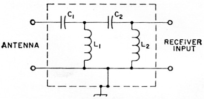
Fig. 1. Circuit of the two-section high-pass filter. Components should be mounted in a grounded metal container. Values shown below are for a cut-off frequency of 3 Mc and a receiver input impedance of 72 ohm. For a different cutoff or termination, see the design information in the text.
| C1,C2 | 400 pF, mica or ceramic. |
| L1,L2 | 1.9 µH, 5 turns No. 22 d.c.c. dose-wound on 1½ inch diem. form. |
It is not essential that C be exactly 370 pF. In the original filter 400 pF capacitors were used because they were on hand. To find the right size coil for L, first calculate the resonant frequency of L and C from the formula
![]()
f will be in Mc. when L is in ph. and C is in pF. Connect the capacitor you are using across a coil and check the resonant frequency with a grid-dip meter. Vary the number of turns or the size of the coil until the meter dips at the calculated frequency; 1.9 µH resonates with 400 pF at 5.8 Mc, and the coils specified check out very close to this frequency.
The filter components should be mounted in a shield can which is grounded when in use. A frozen-orange-juice can with aluminum foil secured over the open end makes a suitable and inexpensive shield. Arrange the coils perpendicular to each other to minimize coupling.
Any number of filter sections can be cascaded. .Two sections did the job for the case in point and removed all spurious signals from the 80 meter band except for two true harmonics.
Notes
- Cross-modulation can also occur in any nearby rectifying circuit - such as a poor contact in water or steam piping in the strong field of the transmitting antenna - external to both receiver and transmitter. The filter described here will clean up only what cross-modulation occurs in the receiver, but even this is an advantage, since it helps fix the blame where it belongs. - Ed.
R.E. Baird. W7CSD.