Radioteletype reception by tone conversion
A complete converter including monitor and a.f.s.k. oscillator.
This high-performance tone converter is all that's needed between receiver output and teletype machine for both f.s.k. and a.f.s.k. reception. The circuit diagrams aren't small, but there's nothing in them that should frighten even a newcomer to RTTY. An oscilloscope-type monitor, audio frequency shift keyer and power supply are all included. Together with the author's i.f. converter article in QST for January, this makes a fine exposition of the methods of radioteletype conversion.
There are two commonly-used methods for receiving radioteletype signals. One is to detect the frequency shift at the receiver i.f. The other makes use of the two audio tones created by beating the receiver b.f.o. against the shifting carrier.
Tone conversion has two advantages over i.f. conversion: Audio filters having a band pass of only 200 or 300 c.p.s. can be used to reduce interference more effectively than the band pass of the i.f. system. The tone method can also be used for reception of modulated signals with audio frequency-shift keying (a.f.s.k.). as is authorized on the v.h.f. bands.
This article will discuss the operation and construction of one type of tone converter as well as accessory circuits such as a tuning oscilloscope and a two-tone generator for a.f.s.k. transmission. Two frequencies have been standardized on for tone conversion. These are 2125 c.p.s. for "mark" and 2975 c.p.s. for "space," and will be the frequencies referred to when the terms mark and space are used.
Operation
Fig. 1 is a schematic diagram of the tone converter proper. Mark and space signals coupled from the receiver through line-to-line transformer T1 are separated by band-pass filters FL2 and FL3. Each filter has a 200-c.p.s. bandwidth centered on its particular frequency and an impedance of 600 ohm.(1) The filter inputs are paralleled. This does not disturb the match because the impedance of either filter is quite high at the center frequency of the other, and only one tone is present at a time. Potentiometer R1 is used to take off part of the incoming signal for the tuning scope of Fig. 3.
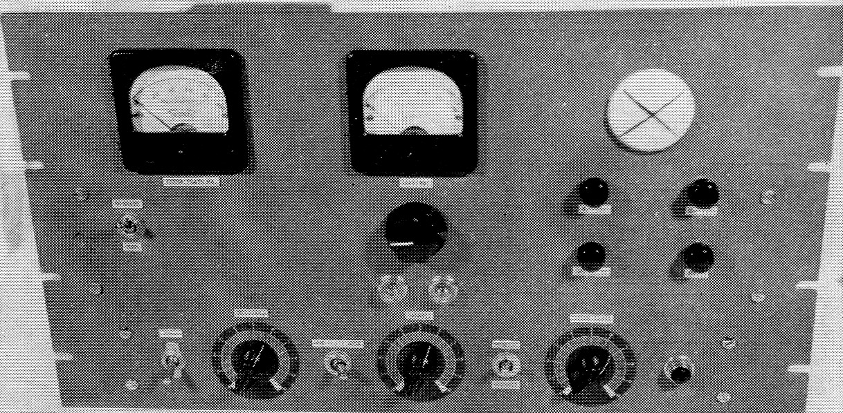
Front view of the tone-conversion unit. The meter on the left indicates keyer plate current, and below it is the TUNE/ OPERATE switch. The meter and control for setting the keying loop current are in the center of the panel, and the two glass domes immediately below are for the NE-51 neon triggers. To the right is the 902A cathode-ray tube used for monitoring. Below the c.r.t. face are the vertical and horizontal centering knobs, and below them are the intensity and focus controls. From left to right across the bottom of the panel are the power switch, the THRESHOLD control which sets the neon firing voltage, the FSK/AFSK switch which transfers the keying loop between an external f.s.k. exciter and the built-in audio frequency-shift keyer, the BALANCE control for setting the relative amplitudes of the mark and space pulses going to the trigger driver, a FORWARD/REVERSE switch to reverse the operation of the detector for signals using the higher frequency on mark, the monitor SCOPE LEVEL control, and a pilot lamp.
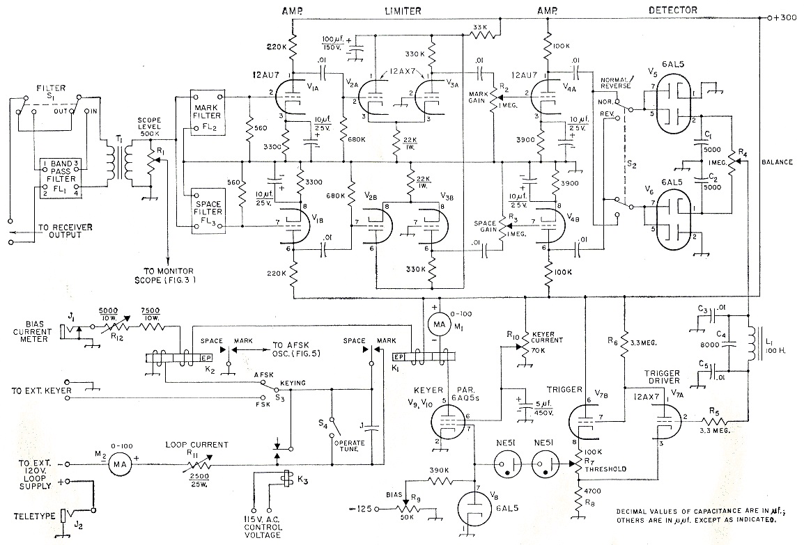
Fig. 1. Circuit of the basic tone converter. Resistances are in ohm; resistors are ½ watt composition except as indicated. Capacitors marked with polarity are electrolytic; others can be either paper or ceramic.
| C1,C2 | 5 nF disk ceramic. |
| C3,C5 | 10 nF paper. |
| C4 | 8 nF paper. |
| FL1 | See Fig. 2. |
| FL2,FL3 | See text. |
| J1 | Closed-circuit jack. |
| J2 | Open-circuit jack. |
| K1,K2 | Polarized relay (Sigma 7AOZ-1 60T or equivalent). |
| K3 | S.p.s.t. relay, 115-volt a.c. coil. |
| L1 | 100 H choke (original taken from BC-733, Stancor C-2301 usable). |
| M1,M2 | 0-100 d.c. milliammeter. |
| R1 | 500 kΩ composition control, audio taper. |
| R2,R3 | 1 MΩ composition control, audio taper. |
| R4 | 1 MΩcomposition control, linear taper. |
| R5,R6 | 3M3, ½ watt. |
| R7 | 100 kΩ composition control, linear taper. |
| R8 | 4k7, ½ watt. |
| R9 | 50 kΩ composition control, linear taper. |
| R10 | 70 kΩwire-wound control, linear taper. |
| R11 | 2k5, 25 watt adjustable. |
| R12 | 5 kΩ, 10 watt adjustable. |
| S1,S2 | D.p.d.t. toggle. |
| S3 | S.p.d.t. toggle. |
| S4 | S.p.s.t. toggle. |
| T1 | Line-to-line transformer (Stancor A-4350). |
FL1, a band-pass filter with cut-off frequencies of 2000 and 3100 c.p.s., can be switched in ahead of the tone filters by throwing Si. This filter is only used under extremely noisy conditions to provide better rejection of random signals.
The separated tones are applied to two separate but identical channels starting off with amplifier stages V1A and V1B, the two sections of a 12AU7. Then each signal is clipped to a level of about 7 volts in cathode-coupled limiter stages V2 and V3, two 12AX7s. Then come equalizing controls, R2 and R3, which are used to compensate for any unequal response in the above stages or the receiver audio section.
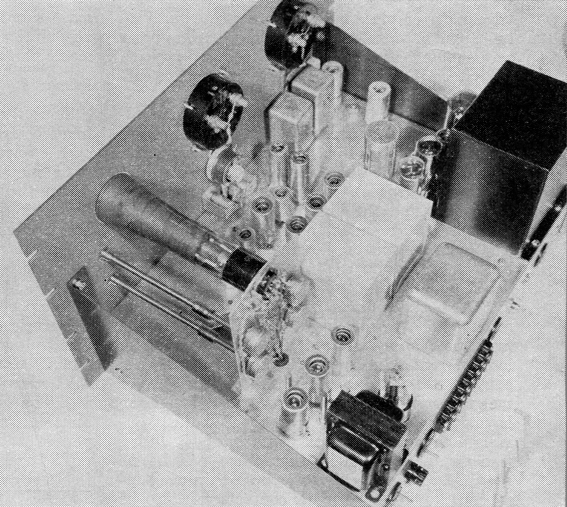
The 902A c.r.t. and the centering, intensity and focusing potentiometers are all mounted on an aluminum bracket fastened to the chassis. The three scope amplifier tubes are toward the rear of the chassis. The high-voltage supply for the c.r.t. is in the bottom corner. Band-pass filter FL; is housed in the aluminum shield can in the center of the chassis near the back. In front of FL; are the hermetically-sealed Gates mark and space filters, and the tone converter tubes are grouped between these filters and the neon sockets on the panel. The polarized keying relays are near the upper corner of the chassis along the panel edge. The two tubes next to them are the a.s.f.k. oscillator and amplifier. Main power transformer T3 is in the right corner, and the 80-0. filter capacitor and regulator and rectifier tubes are lined up in front of it.
After additional amplification in V4, another 12AU7, the tones are rectified by voltage-doubling detectors, V5 and V6, two 6AL5s. C1 and C2 bypass the audio components. On mark about 80 volts negative is applied to the upper end of balance control R4, and on space about 80 volts positive is applied to the lower end of R4. Throwing S2 reverses the action for any signals which use the higher frequency for mark instead of space.
The arm of R4 connects to a low-pass filter made up of L1, C3, C4 and C5. This filter cuts off at about 140 c.p.s. and helps to remove noise and keying transients. From the filter the signal passes through isolating resistor R5 to the grid of trigger driver V7A. This 12AX7 section is directly coupled to V7B, the trigger stage. When a negative mark pulse appears on the grid of V7A, plate current to that stage is cut off, and the plate voltage rises to the supply value. Since the plate of V7A is connected to the grid of V7B, the latter will conduct and there will be a large voltage drop across cathode resistors R7 and Rs. Therefore, the two NE-51 neon lamps will fire through the 6AL5 diode, Vs. R7 is a threshold control and is set so that the neons show a normal orange glow under these conditions. Positive space pulses cause the trigger driver plate current to increase until all but about 2 volts of the supply voltage appears across plate load resistor R6. The reduced positive voltage on the grid of V7B decreases its plate current and extinguishes the neons.
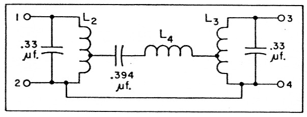
Fig. 2. Schematic of the band-pass filter marked FL1 in Fig. 1. Capacitors are molded paper and should be within 5 per cent of the values shown.
| L2,L3 12.3 mH; 272 turns No. 24 Formvar on toroidal form with ¾ inch mean diameter, tapped 68 t. from bottom end. (May be wound 4-filar; see text.) |
| L4 10.3 mH; 248 turns No. 24 Formvar on toroidal form with ¾ inch mean diameter. |
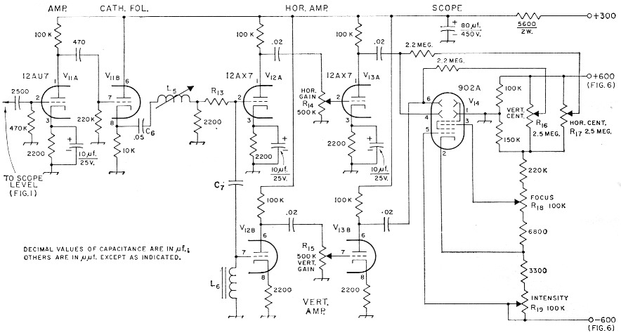
Fig. 3. Circuit of the monitoring oscilloscope. Resistances are in ohms; resistors are 1/2-watt composition except as indicated. Capacitors with polarity marked are electrolytic; others are ceramic except as specified.
| C6 | 50 nF molded paper. |
| C7 | About 30 nF mica (to resonate with L6 at 2550 c.p.s.). |
| L5 | 120 mH TV width control (similar to Miller 6324). |
| L6 | 100 to 500 mH toroid (to resonate with C6 at 2550 c.p.s. similar to UTC MQA-7). |
| R13 | About 4700 ohm, 1/2 watt (see text). |
| R14,R15 | 500 kΩ composition control, audio taper. |
| R16,R17 | 2M5 composition control, linear taper. |
| R18,R19 | 100 kΩ composition control, linear taper. |
Two 6AQ5 keyer tubes, V9 and V1o, are paralleled to handle a current of 60 ma. R9 is used to set the negative grid bias to a value above cutoff (about 45 volts) when the neon lamps are not conducting (space). During mark pulses the neons fire, and the bias voltage is neutralized; then the 6AQ5s conduct, operating polar relay K1. The plate current of the keyer tubes is metered by Ml and adjusted to 60 ma. with screen-voltage control R10.
The mark contacts of K1 are connected in series with a 60-ma. local loop. With S3 in the AFSK position as shown, this loop consists of loop current adjustment R11 and meter M2, an external 120-volt d.c. supply, the teletype selector magnet circuit (connected through J2) and the keying coil of AFSK polar relay K2. Relay K3 is used to short the mark contacts of K1 during transmitting periods so that there will be no possibility of a circuit interruption causing erroneous keying. The mark contacts can also be shorted with OPERATE-TUNE switch S4.
The converter was designed to be compatible with an f.s.k. exciter requiring 60 ma. for its keying circuit, and S3 transfers the 60-ma. loop current from the a.f.s.k. relay to a pair of terminals provided for the exciter. Bias current of 30 ma. for both polar relays is taken from the 300-volt plate supply; the current is measured with a meter plugged into Ji and adjusted with R12.
Monitor scope
Since the converter operates with two audio frequencies which must be held within a few cycles tolerance, it is quite desirable to have some method of monitoring these frequencies. About the best method the writer has found is the c.r.t. display circuit designed by W0HZR(2) and modified for use in this converter.
Fig. 3 is a diagram of the monitor. The heart of the unit is the phase-shift circuit consisting of R13, C7 and L6 in series. C7 and L6 are resonated at 2550 c.p.s., halfway between the mark and space frequencies of 2125 and 2975 c.p.s., respectively. The voltage across C7 and L6 is amplified by 12AX7 sections V12A and V13A and applied to the horizontal deflection plates of the 902A c.r.t., V14. The voltage across L6 is amplified by V12B and V13B and applied to the vertical deflection plates.
The trace displayed on V14 depends on the frequency or frequencies fed to R13. At the resonant frequency, 2550 c.p.s., the voltage across the CALS combination is very small compared with that across L6, and the trace is a vertical line. At higher frequencies the horizontal signal is larger than the vertical one, and both are in phase. The resulting trace is a line that slopes up to the right. The horizontal signal also increases at frequencies below 2550 c.p.s. but is 180 degrees out of phase with the vertical signal. For these frequencies the trace will be a line sloping up to the left. The relative gains of the horizontal and vertical amplifiers can be adjusted so that the mark and space frequencies produce the arms of a perfect 90-degree "X" on the c.r.t. face. So adjusted and calibrated, the scope will disclose several things about the incoming signal as shown in Fig. 4.
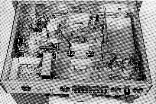
Some parts in this bottom view can be identified by comparison with the top view. The a.f.s.k. oscillator and amplifier components are in the upper left. The oscillator inductance, L7, is the dark object between gain control Rm. on the left and the line-to-line transformer. Resonating capacitors C7 and C9 are just below L7 in this view. Farther toward the back of the chassis are shorting relay K3 and the controls for setting keyer-tube screen voltage and grid bias. Filter capacitors C11 and C12 and choke La are mounted underneath the power transformer. The switch for Fl1 is just visible to the right of la, and input transformer T1 is mounted between the terminals of FL1 and the mark and space filters. Toward the front of the chassis is the converter section, where much of the wiring is done to ground and high voltage bus wires running between tie points. The metal can between the converter tubes and the panel is low-pass filter inductor, L1. The extension shaft to the right connects the SCOPE LEVEL control, R1, with its panel knob. The monitor scope amplifiers and power supply are in the lower right-hand corner. From left to right along the rear apron are J2, the jack for connecting the teletype printer; a 115 volt accessory socket; bias current jack J1; bias current adjustment Kw and another accessory socket. Then comes a terminal strip for making connections to the receiver output, the f.s.k. keyer, the 120-volt loop supply, and modulator of a v.h.f. transmitter for a.f.s.k. Finally, there are male a.c. connectors for the power supply and control relay, K3 and the power-supply fuse.
Mark and space signals from voltage divider R1 in Fig. 1 are amplified in V11A, one section of a 12AU7. Follower stage V11n cathode-couples the tones to series-tuned circuit C6L5 resonant at about 2200 c.p.s. This provides slight peaking at the mark frequency and compensates for the lower Q of the phase-shift network at 2125 c.p.s.
R14 and R15 are used to adjust the gains of the horizontal and vertical amplifiers. Since much less gain is required in the vertical channel, the cathodes of V12B and V1313 are left unbypassed as shown.
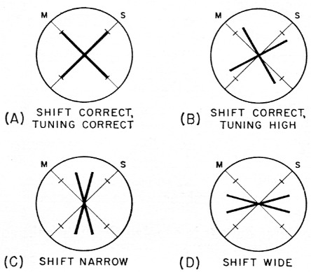
Fig. 4. Patterns observed on the monitor scope. Horizontal and vertical gain controls should be set so that mark and space signals of correct frequency and spacing will produce a perfect 90-degree "X" as in (A). (B), (C) and (D) show the effects of incorrect tuning and frequency shift.
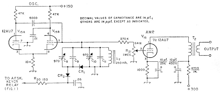
Fig. 5. Circuit of the a.f.s.k. oscillator section. T2 feeds the carbon microphone input of a v.h.f. transmitter. Resistances are in ohm; resistors are ½ watt composition except as indicated. Capacitors with polarity marked are electrolytic; except for the 5 nF capacitor which is mica; others are ceramic except as specified below.
| C8,C10 | 970 pF mica trimmer. |
| C9 | About 12n8 mica (as required to resonate with C8-C10-C11-L7 at 2125 c.p.s.). |
| C11 | About 10 nF mica (as required to resonate with C10-L7 at 2975 c.p.s.). |
| CR1,CR2 | 1N34 or equivalent. |
| L7 | 100_300 mH (250 mH toroid similar to UTC MQE-9 used in original). |
| R20 | 150 Ω, ½ watt. |
| R21 | l MΩ composition control, audio taper. |
| T2 | Tube-to-line transformer (Stancor A-3250). |
A conventional voltage-divider circuit is used to obtain centering, focusing and intensity potentials for the 902A.
Audio frequency-shift oscillator
A.f.s.k. operation on the v.h.f. bands requires an audio oscillator for producing the mark and space tones. Such an oscillator was incorporated on the converter chassis. The circuit, shown in Fig. 5, is a slight modification of one used by W2JTP.(3)
V15, a 12AU7, functions as a cathode-coupled, diode-keyed oscillator. The diodes, CR1 and CR2, are in turn controlled by polar relay K2 in the loop circuit. On mark, K2 grounds the lead from R20, and on space, this lead is left open. In the latter condition there is no d.c. path through CR1 and CR2, and they do not conduct. The diodes then appear as small capacitors of about 1 pF, and the frequency of oscillation is determined essentially by the C10C11L7 parallel combination. C10 tunes the combination to the space frequency. When R20 is grounded, rectification of the audio voltage across CR1 causes a current to flow through CR1, CR2 and R20. The resistance of CR1 drops to a low value, and C8 and C9 are effectively paralleled with C10C11L7. Trimmer C8 adjusts this new combination to resonance at the mark frequency.
Oscillator output is coupled through gain control R21 to the grid of amplifier stage V16, one section of a 12AU7. T2 matches the output of this amplifier to a 500-ohm line which can be connected directly to most carbon microphone input circuits.
Power Supply
The built-in power supply, diagrammed in Fig. 6, provides all necessary voltages for the converter, scope and a.f.s.k. oscillator. T3 supplies 150 volts regulated for the oscillator and 300 volts regulated for the remaining stages through full-wave rectifier V17, a capacitor-input filter and regulators V18 and V19. A half-wave rectifier, V20, connected to one end of the secondary of T3, is used to get 125 volts of negative bias for the keyer tubes.
T4 and half-wave rectifier V21 supply 600 volt for the c.r.t. The 6.3 volt winding on T4 takes care of the 902A heater, which must be ungrounded because of the high negative voltage on the cathode.
Accessory sockets J4 and J5 can be used for auxiliary equipment and are controlled by power switch S5.
Construction notes
The converter and its associated circuits are built on a 17 × 13 × 3 inch chassis with a 19 × 10½ inch panel for standard rack mounting. The locations of most components can be discovered from the photographs and their captions. Since only audio frequencies are involved, layout is not critical.
Toroids L2 and L3 are tapped ¼ of the way from one end, so it may be easier to wind these coils 4-filar. To do this, start with four wires and wind them together around the core. Each wire then becomes ¼% of the coil if properly connected to the others. Take one of the wire ends that went on the core first as the bottom end of the coil. Connect the other end of that wire to the starting end of a second wire; this is the tap point. Now connect the other end of the second wire to the starting end of a third wire and the other end of the third wire to the starting end of the fourth wire. The other end of the fourth wire will be the top of the coil.
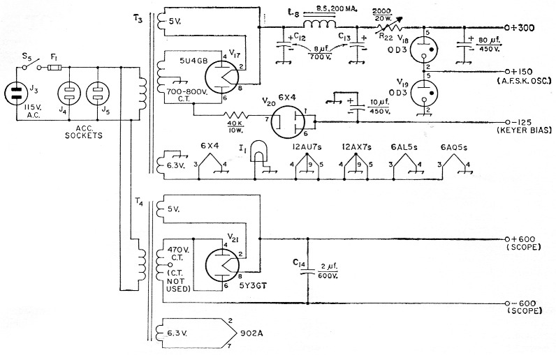
Fig. 6. Power-supply section. Resistances in ohms; resistors are wire-wound; capacitors are electrolytic except as specified.
| C12,C13 | 8 µF 700 volt electrolytic (Aerovox 07B1 10). |
| C14 | 2 µF 600 volt bathtub (Aerovox P3OZN). |
| F1 | Fuse (rating determined by accessory load). |
| I1 | 6.3 volt pilot lamp. |
| J3 | 115 volt male connector, chassis mounting (Amphenol 61-M). |
| J4,J5 | 115 volt female connector, chassis mounting (Amphenol 61-F). |
| L8 | Filter choke, 8.5 H at 200 mA (Stancor C-1721) |
| R32 | 2000 ohm, 20 watt adjustable. |
| S5 | S.p.s.t. toggle. |
| T3 | Power transformer, 800 volt c.t.; 200 mA; 5 volt, 3 A; 6.3 volt, 5 A (Stancor PC-8412 suggested). |
| T4 | Power transformer, 470 volt c.t., 40 mA; 5 volt, 2 A; 6.3 volt, 2 A (Stancor PC-8401). |
It is recommended that an audio generator and oscilloscope be used to get the tuned circuits of the monitor scope and a.f.s.k. oscillator properly adjusted. The oscilloscope should also be used to check pulse shaping in the tone converter.
The value of R13 determines the band-pass chracteristics of the C7L6 resonant circuit in the monitor. If the trace obtained at 2550 c.p.s. is much larger than those at the mark and space frequencies, then the value of R13 is too small.
The toroid or coil used for L7 in the a.f.s.k. oscillator should not have too high a Q or the frequency shift during shorter pulses will be incomplete.
Notes
- These filters can be obtained from William Gates, 15183 Encanto Drive, Sherman Oaks, Calif., for $25.00 per pair, f.o.b. Los Angeles.
- Meyer, "F.S.K. Tuning Indicator," CQ, May, 1956.
- Kretzman, "W2JTP a.f.s.k. oscillator," The Radio Amateur's RTTY Handbook, 1957. This circuit originated with Bernstein, who used it for r.f. keying; see
"Some notes on frequency-shifting crystal oscillators," QST, July, 1953.
James L. McCoy, W0LQV/AF0LQV.