A cathode-ray transmitter monitor
Incorporating the most needed features for amateur radio.
The circuit that is the subject of this article was designed solely for the purpose of checking and monitoring amateur transmitters. It incorporates a number of features - such as tuned ham-band r.f. input, send-receive blanking, and audio phase correction - that are not found in scopes built for general measurement work.
The cathode-ray monitor to be described will display either the r.f. envelope or the trapezoidal monitoring pattern of single-sideband or amplitude-modulated transmitters. It will show linearity or nonlinearity in Class B r.f. amplifiers, parasitic oscillation, neutralization, and r.f. output. The cathode ray beam responds instantly and provides information that moving coil meters can never provide. In addition, it gives a continuous complete picture of the overall performance of the transmitter - and we can all understand pictures.
The monitor shown here was designed to remedy the annoyances and shortcomings of oscilloscope lash-ups, which have had a habit of growing like Topsy: external tuned circuits hung on the input terminals, the wrong sweep, uncompensated phase shift, no blanking so that the tube became burned or - even worse - the intensity turned down so that the scope does not fulfill its function of monitoring, and so on. Nevertheless, Fig. 1 shows that the circuit is relatively simple and straightforward.
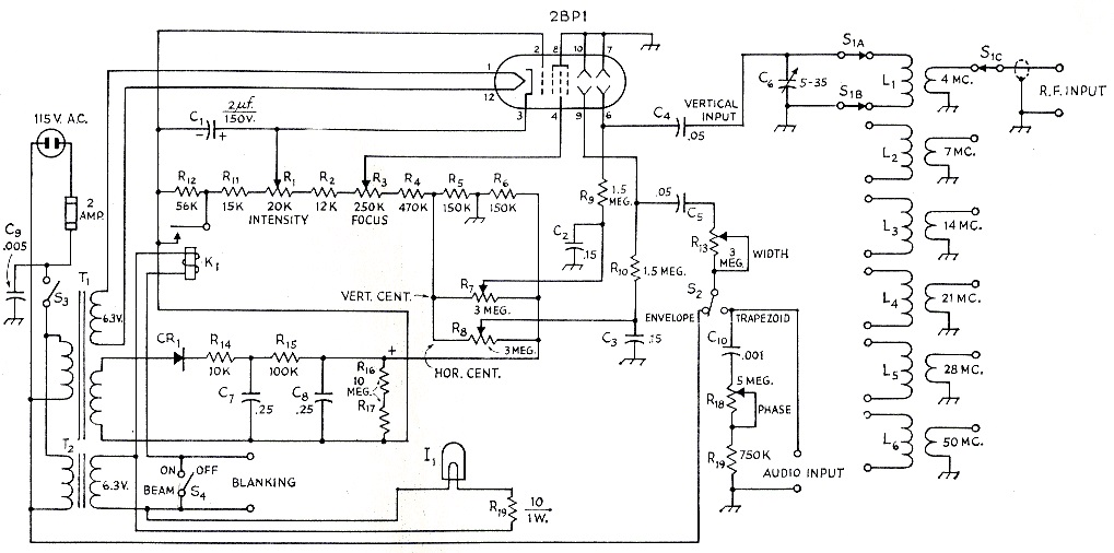
Fig. 1. Circuit diagram of the cathode-ray monitor. Unless otherwise indicated, resistances are in ohm, fixed resistors are ½ watt composition; decimal values of capacitance are in µF, others in pF.
| C1 | Electrolytic. |
| C2,C3,C4,C5 | 400 volt paper. |
| C6 | 35 pF midget variable (Millen 20035). |
| C7,C8 | 1500 volt oil-filled paper. |
| C9 | Mica. |
| C10 | Disk ceramic. |
| CR1 | See text. |
| I1 | No. 44 dial lamp (0.25 amp.). |
| K1 | S.p.s.t., 6.3 volt a.c. coil (Potter-Brumfield CA3A). |
| L1 | 90 turns No. 34 enam., close-wound. Link 3 turns No. 28 enam. |
| L2 | 45 turns No. 28 enam., close-wound. Link 3 turns same. |
| L3 | 17 turns No. 28 enam., close-wound. Link 3 turns same. |
| L4 | 8 turns No. 28 enam., close-wound. Link 2 turns same. |
| L5 | 5 turns No. 28 enam., close-wound. Link 2 turns same. |
| L6 | 2 turns No. 28 enam., spaced Ye inch. Link 1 turn No. 28. |
| R1,R3,R7,R8,R13,R18 | Carbon control, linear taper. |
| S1 | Phenolic rotary, 3 sections, 3 poles, 6 positions, nonshorting. |
| S2 | S.p.d.t. toggle. |
| S3,S4 | S.p.s.t. toggle. |
| T1 | See text. |
| T2 | 6.3 volt filament transformer, 1.2 amp. |
All coils wound on 1/2-inch diam. polystyrene forms (Millen 47001) with link at top. Upper end of tuned winding connects to chassis ground.
The heart of the monitor is the 2BP1 two-inch cathode-ray tube. Experiment with one-inch tubes, two-inch round and rectangular tubes, and three-inch round and rectangular tubes showed the two-inch round tube to be the best choice for the job. The two-inch round tube provided an entirely adequate display of envelope, trapezoid, and bow-tie patterns. The one-inch display seemed inadequate. The rectangular tubes were fine for envelope display but the vertical height proved inadequate for trapezoidal and bow-tie monitoring. The three-inch round tube provided good display but was no longer compact.
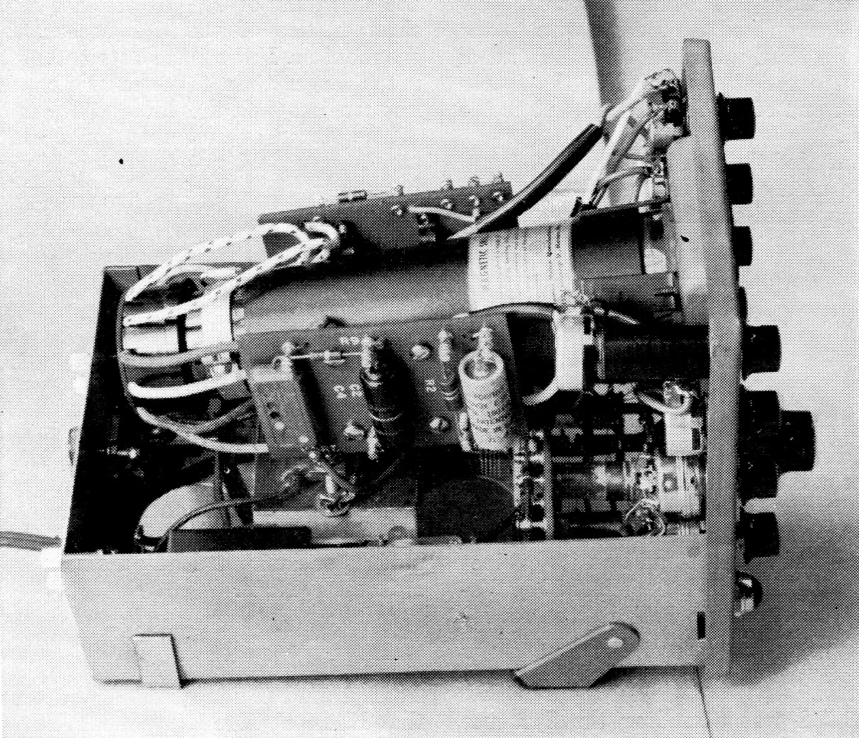
This is a manufactured version of the circuit, and although its mechanical construction could not be duplicated with ordinary home-workshop facilities, it illustrates some features that are desirable in any scope layout. One is the magnetic shield, which in this case is a type (such as the Millen 80042) that serves as a support for the cathode-ray tube and includes a base clamp for secure positioning. A molded bezel supports the face of the tube and dresses up the panel. Another feature is the mounting of the intensity control, which is at high voltage with respect to the chassis; it is on an insulated extension coupling (Millen 39023) as shown in the near corner of the panel. The principal constructional point is that a really effective magnetic shield should be used so that magnetic fields from the power transformer will not influence the beam.
Two-inch tubes are fairly insensitive, particularly when the accelerating voltage is high enough to give a bright, sharp trace. However, in this monitor lack of sensitivity proved to be no problem. In fact, with the link-coupled tuned circuits feeding the deflection plates, the monitor is so sensitive that a grid-dip meter coupled to the pickup loop provides usable vertical deflection. The horizontal deflection voltage for the envelope display is easily provided by the 115 volt 60 cycle power source.
Power supply
The over-all power-supply voltage is slightly over 1000 volts d.c., but since the maximum current drain is only 1% ma. the power transformer can be quite small. The most economical way to get this voltage is to use a replacementtype power transformer rated at 700 to 750 volt total secondary voltage. Such a transformer will have the 6.3-volt winding for the 2BP1 heater and will also have a 5-volt winding that can be used for the rectifier, which may be a 2X2A, 5R4GY, or other tube having sufficient voltage rating (some tubes may require dropping the heater voltage to the rated value). Selenium rectifiers may be used instead of a tube, six of the ordinary 130-volt type being required in series to stand a.c. voltages of this order. However, the smallest current rating available can be used, so the cost does not greatly exceed that of a tube rectifier.
An R-C filter is used to smooth the half-wave rectified d.c. so that the remaining peak-to-peak ripple is only about 0.35 per cent. R14 is used to limit the charging current of C7 and thus protect the rectifiers. The filter capacitors are rated at 1500 volts d.c. working because the peak voltage is quite substantial.
All d.c. voltages are taken from the series divider made up of R1, R2, R3, R4, R5, R6, R11 and R12. This divider is directly across the output of the filter system. A high-resistance bleeder, R15R17, is also used, for reasons of safety. The bleeder uses two resistors so that the voltage across any one resistor will not be excessive.
A separate 6.3 volt filament transformer is used to operate the beam blanking relay and pilot light, because the 6.3-volt winding that supplies the 2BP1 heater is several hundred volts above chassis. The separate transformer avoids the possibility of voltage breakdown in the relay.
Balanced deflection and balanced centering are not required for the 2BP1 tube. This greatly simplifies the circuit and construction. If tubes other than the 2BP1 are used, it is quite likely that keystone distortion (greater deflection sensitivity at one side of the tube than at the other) will result.
The intensity control is at a very high negative potential with respect to the chassis and must be insulated from it. Although the current available may not be enough to cause death, contact with the high voltage can be very painful. Use caution!
Vertical deflection circuit
Low-voltage r.f. can be picked up by means of a small single-turn coil loosely coupled to the transmitter output circuit, the antenna matching circuit or any other convenient point. If a multiple outlet box is used in the feed line, one outlet jack can have a small loop across it. The pickup loop can be connected through a convenient length of small coaxial cable to the terminals marked "r.f. input." One wafer of S1, the band switch, selects the link coil coupled to the desired tuned circuit, and the other two wafers of Si select the coil to be placed in the tuned circuit.
The relatively high r.f. voltage developed across the tuned circuit is coupled to the c.r. tube vertical deflection plates through a blocking capacitor, C4, so the coil will not short-circuit the d.c. centering voltage. R9 and C2 make up a filter network to prevent the r.f. from going back to the centering-voltage supply.
Horizontal deflection circuit
For trapezoidal or bow-tie display, audio voltage from the output of the transmitter modulator must be supplied to the audio input terminals. C10R13R19 is a phase-shift network for precise audio phase correction. The phase-corrected audio is applied to the " width" control, R13, through S2. The output of the width control goes to the horizontal deflection plates through C5. An audio filter network, C3R10, prevents the audio from getting to the centering supply.
For envelope display the horizontal sweep voltage, applied to the width control through S2, is a 60 cycle sine wave taken from the 115 volt line.
Blanking
The blanking bias is developed across R12. When the relay is closed, R12 is shorted out and the normal bias developed across R11 and R1 fixes the trace intensity. The relay may be operated either by the transmitter send-receive relay or by the "beam" switch, S4. When the beam switch is on, the relay is closed and the transmitter switch can no longer control. A cable should be run from the blanking terminals to an extra set of contacts on the transmit/receive relay. This method of blanking is positive and requires no careful adjustment of anything. It would be easy to rectify a little of the r.f. voltage to provide the blanking but this requires careful adjustment of the r.f. level. The relay was quite inexpensive and seemed a good investment in reliability.
Installation
Three cables connect the monitor to the transmitter. The one which connects to the r.f. input terminals should be a small-diameter coaxial cable with a single-turn loop coupled to the transmitter r.f. output, as already described. The cable which feeds audio into the monitor should be connected to the audio output of the transmitter. On an a.m. rig it may be necessary to install a high-resistance voltage divider across the secondary of the modulation transformer.(1) The coupling capacitor should have a high enough d.c. rating to withstand the peak voltage on the secondary of the modulation transformer - this is about twice the plate-voltage supply to the final r.f. amplifier. Some modulators have a built-in divider to supply audio to a monitor. It is important to connect to the output of the audio system rather than to some other point in the modulator.
On a single-sideband rig of the phase-shift type, the audio should be picked up at the input to the audio phase-shift network. On a filter rig the audio should be picked up at the input to the balanced modulator.
If the audio level at the pickup point in the s.s.b. transmitter is too low to provide adequate display width, it will be necessary to use additional amplification. Fig. 2 shows a circuit which can provide full horizontal deflection without distortion with an input of 0.6 volt r.m.s. It is essential that there be an input gain control, R1, in the amplifier, to avoid overdriving the grid of the first triode section. This amplifier requires only 2.6 mA at 315 volt d.c. and heater voltage of 6.3 volt a.c. at 0.3 amp. It can be tucked into the transmitter or into a corner of the monitor oscilloscope. In most applications it will be possible to take the required power from the transmitter.
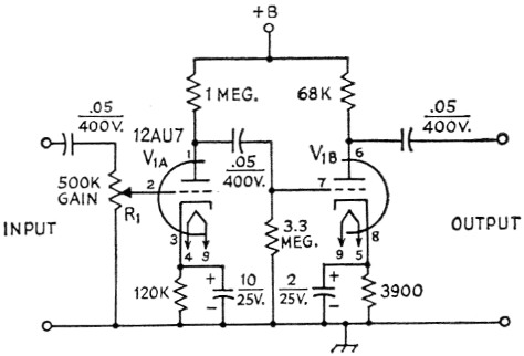
Fig. 2. Audio preamplifier for use with low-level modulators. Unless otherwise indicated, resistances are in ohms, fixed resistors are /-watt composition; capacitances are in µf.; capacitors with polarities marked are electrolytic, others are paper. Power requirements are 2.6 mA at 315 volt d.c. and 0.3 A at 6.3 volt a.c.
R1 Carbon control, audio taper.
If only envelope display is required, no connection need be made to the audio terminals on the monitor. For monitoring purposes; the envelope display is adequate, but the trapezoidal and bow-tie displays divulge more information about linearity.
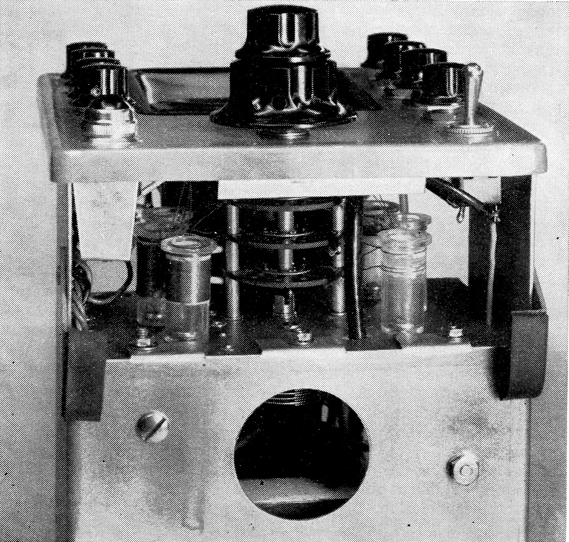
The coils for the tuned circuits are mounted in a circle around the band switch. Input links connect to the r.f. terminals on the rear of the chassis through a length of coax. The leads from the tuned-circuit coils to the deflection plates should be kept reasonably short.
An interesting space-saving feature here is the use of a switch with concentric shafts, the inner one being used to operate the tuning capacitor.
The cable to the blanking terminals should connect to a pair of contacts on the send/receive switch (or relay) or the VOX relay. The contacts should close when the transmitter is on.
Checking and trouble shooting
The monitor is relatively simple and probably will work properly immediately on completion. In a circuit which contains six potentiometers, it is often possible to have one or more wired so that it functions backward, but this is easily remedied. The d.c. supply voltage may be checked with a d.c. v.t.v.m. Since the voltage will exceed 1000 volt, it may be necessary to connect a resistor (10 megohms, % watt, will do) in series to put the reading on scale; it is then necessary to determine the multiplying factor by measuring a voltage which is between 500 and 1000 volt, first without the multiplier and then with it. If the power-supply voltage is significantly under 1000 volt , the wiring should be checked. Do not attempt to measure the voltage with a low-resistance voltmeter as it will draw enough current to cause considerable voltage drop in R15.
With the transmitter off but with 24 closed and S2 at "trapezoid," a small bright spot should appear on the face of the cathode-ray tube when R1 is turned clockwise. Adjust R1 so the spot is not too bright and then adjust R3 for the smallest (sharpest focus) spot. If no spot appears, set R1 full clockwise and set R3, R7 and R8 at about half scale. If all is well, a spot will appear, but if not, check the voltage between chassis and either end of R9. It should be possible to set this voltage to zero by adjustment of R7. If there is still no spot, check the voltage between chassis and either end of Rio; it should be possible to set this voltage to zero by adjustment of Rs. If there is still no spot, check to be certain that R12 is shorted out by the relay. Once a focused spot is on the face of the tube, it should be possible to blank it out by turning RI counterclockwise.
Next, set S2 to "envelope." The spot should become a line. It may be necessary to advance R1 slightly clockwise. If no line, set R13 to about half scale and try reversing the polarity of the power cord. If there is still no line, check the wiring of C9, S2, R13 and C5.
With a line on the face of the tube it should he possible to control its length by R13 and its sharpness by R3.
If the line is not horizontal, note approximately how much rotation of the tube is required to make it so, shut off the monitor and rotate the tube; then turn the monitor on and get exactly the right position, being very careful to touch only the socket and not the wiring. Shut off the monitor again and secure the tube without allowing it to rotate. Proper alignment of the trace will result when the tube locating pin is at about 11 o'clock. viewed from the front.
Clockwise rotation of Rs should move the line to the right and clockwise rotation of R7 should move it up. If both directions are backward, the tube is upside down. If only one direction is wrong, check the wiring of the centering control and the deflection plates.
Operation
With S2 on "envelope," set the monitor band switch, Si, to the desired band and turn on the transmitter. With an unmodulated a.m. transmitter or an s.s.b. transmitter with single-tone modulation, adjustment of C6, the monitor tuning capacitor, should produce a smooth rectangular raster whose height can be controlled by the tuning knob. With no modulation on an s.s.b. transmitter only a horizontal line should appear if the carrier suppression is adequate. If the height of the raster cannot be controlled satisfactorily, it may he necessary to adjust the position of the pickup loop at the transmitter. If the raster appears at one end of the capacitor range, the circuit is not tuning properly; note the position of the capacitor rotor and make the required alteration in the coil. If no raster appears, check the cable, pickup loop, and the wiring of SI and the coil in use.
After a satisfactory raster is on the tube face, apply a test tone to the a.m. transmitter. Since the horizontal sweep on the monitor is 60 cycles, the frequency of the test tone must be very close to some harmonic of 60 cycles to give a recognizable envelope pattern. At 100 per cent modulation the down peaks thin just to points. If these points become lines, the transmitter is over-modulated and splatter is resulting. Adjust the tuning control for convenient height of the peaks, and mark the height when there is 100 per cent sine-wave modulation. Regardless of meter indications, this point represents 100 per cent upward modulation.
In the case of an s.s.b. transmitter, a two-tone test signal must be used. Adjust the transmitter audio level so that there is no flattening at the peaks.
The tuning control on the monitor need not be adjusted for maximum height; it is necessary only that the height be sufficient for convenient viewing.
With S2 in the "trapezoid" position, single-tone modulation on an a.m. transmitter should cause a trapezoid to appear on the monitor tube. If not, check the wiring of S2 and the audio connections at the transmitter. When the trapezoid becomes a triangle, 100 per cent modulation is indicated. Overmodulation will put a horizontal spike at the point of the triangle. If the top and bottom of the trapezoid are elliptical instead of straight lines, adjust the phase control, R15, so that a single sharply-focused trapezoid is displayed. If it is not possible to set the phase control properly or if it does not function at all, check the wiring of Clo and R18. If R13 cannot adjust the trapezoid width properly, adjust the voltage divider at the modulator.
After completing the performance check, turn the beam switch to "off" so the scope pattern will appear only when the transmitter is on.
Applications
Since the monitor is quite sensitive, it may be used as a neutralization indicator. Use the envelope display. Remove the plate and screen voltage from the stage to be neutralized, and couple the monitor pickup loop fairly tightly to the plate circuit of the stage to be neutralized. Apply excitation and tune both the plate circuit of the transmitter and the monitor for maximum raster height. Adjust the neutralization control for minimum raster while keeping the plate circuit tuned for maximum raster. This method of neutralization indication is considerably more sensitive and simpler than using meters.
The linearity of a modulated r.f. stage is best studied by the trapezoidal display. At 100 per cent modulation, the sides of the triangle should he straight lines. Leveling off at the top indicates flattening of the peaks. In a.m. this is usually an indication of insufficient r.f. excitation or of insufficient modulator power. In the case of an s.s.b. linear amplifier, such flattening indicates either overexcitation or poor driver regulation. The flat-topped envelope corresponds to this flattened triangle display.
With an s.s.b. linear amplifier, a two-tone test signal should result in a straight-sided symmetrical display with no discontinuity at the point of crossover. This is true whether the envelope or double trapezoid display is used. Excessive bias will result in a narrow envelope with discontinuities at crossover. Too much drive or incorrect loading will cause a fat rounded envelope.
Parasitic oscillations usually cause drastic discontinuities in the smooth patterns which should result from sine-wave modulation. Although the display of a parasitic is often quite beautiful to look at, it certainly does not sound beautiful on the air.
Conclusion
It is not within the scope of this article to discuss the various possible transmitter difficulties, the patterns indicating them, or their cure. This subject has been covered thoroughly in the literature.(2) Suffice to say that a short period of use of the cathode-ray monitor will show that it is absolutely essential for a modern phone transmitter, be it a.m. or s.s.b., filter or phase shift.
Notes
- See chapters on radiotelephony and speech equipment, The Radio Amateur's Handbook.
- For example, The radio amateur's handbook and single sideband for the radio amateur.
R. Wade Caywood, W1KRD.