A synched-multivibrator electronic key
There are nearly as many different attitudes toward what constitutes the "best" electronic keyer as there are c. w. men. Here's W4DFR's version with one-knob speed control, no relays and a built-in sidetone monitor.
Combined key, keyer and monitor with no relays.
Since the very beginning of the electronic key there has been considerable circuit development aimed at a hand sending device that would imitate the perfection of punched tape code. Stich keys tend to make for pleasant receiving, but they can also place a strain on the sending operator, particularly if he is called upon to send at various speeds. While the keyer described here is not offered as a machine for perfect sending, we do think it is an economical step in the right direction for better and easier sending.
Even a Novice can learn to send with this key and do it better than with a straight key because the uniform characters are more readable. Yet the manual control is flexible enough so that it need not make a robot out of the operator and wipe out every trace of style. Sometimes in "pushing" a key, one will hit the dot post a split second too soon after a dash. At high speeds with a self-completing type key the dot may never be formed and the letter will be wrecked. With this key the dot will be made and the character will be readable even if the space is a bit short.
A few words about code: Code characters and words can be broken down into basic timing elements called bauds. A dot tone and the space following it are each considered as one baud. A dash tone is three bauds and its following space one baud. Thus in a string of dots and dashes the tones are in a 1 to 3 ratio but the total time for dots is half the time for dashes since the space is one baud in each case. Now the old-timer who is used to reading most anything and sends on a "bug" rarely notices differences in these ratios from one speed to another. In fact, most of us will set the weights on the dot lever at about 25 w.p.m. and attempt to send slowly by making rather long dashes and to send fast by making short dashes. It is not uncommon to hear code speed extended from 12 to 30 w.p.m. without any adjustment of the key mechanics. Sometimes an operator will attempt to QRS by making sideswiping motions on the dash post, and it is very difficult to send well by this method. The only sure cure for these bad habits is to have a system which simultaneously expands and contracts the dots, dashes and spaces. With this keyer, only one knob is ever used to adjust for different rates of sending, and this control works from about 8 w.p.m. until one's reflexes fail to register.
The clacking of relays operating at their best is bothersome, and later in their life they tend to stick and be generally unreliable. This keyer is absolutely silent in operation, since it has no relays to clack or adjust. It also features a side-tone keying monitor that operates independently but simultaneously with the transmitter keyed circuit. The keyer will operate in adapted cathode keying circuits up to the current limitation of the keyer tube, and it will also work with transmitters that use grid block keying. All parts are standard, and the cost should not exceed $30.00 if everything must be purchased new.
Those who have tried multivibrator key circuits in the past have experienced erratic operation. A free-running multivibrator is very much like a beagle hound - it will take off and follow any tramp who whistles. In short, it will react to very weak alternating voltages from remote sources. However, this also has its advantages, for a multivibrator will synchronize with an a.c. voltage of desirable frequency and sufficient amplitude introduced at the proper place. In this keyer a generated audio voltage is introduced into the timing circuit. The amplitude of this synchronizing voltage is made just high enough to trigger the multivibrator circuit at regular intervals, and these intervals are controlled by adjusting the speed control. The same method is used to synchronize the sweep of an oscilloscope so waveforms can be viewed. In the time base of a scope, the reverse phase is made as short as possible and often blanked out (return trace), but in the keyer this is not the case. The reverse phase has a specific time that is equal to the desired space time between the dots and dashes. Another portion of the timing circuit operating in the opposite phase can be used to make the tone time of either a dot or a dash. Once the relative lengths of these times are set up, the actual lengths can be expanded or contracted without changing the ratios. Adequate control voltage is supplied to the timing circuits so they will not be subject to extraneous influences like hum or r.f. pickup.
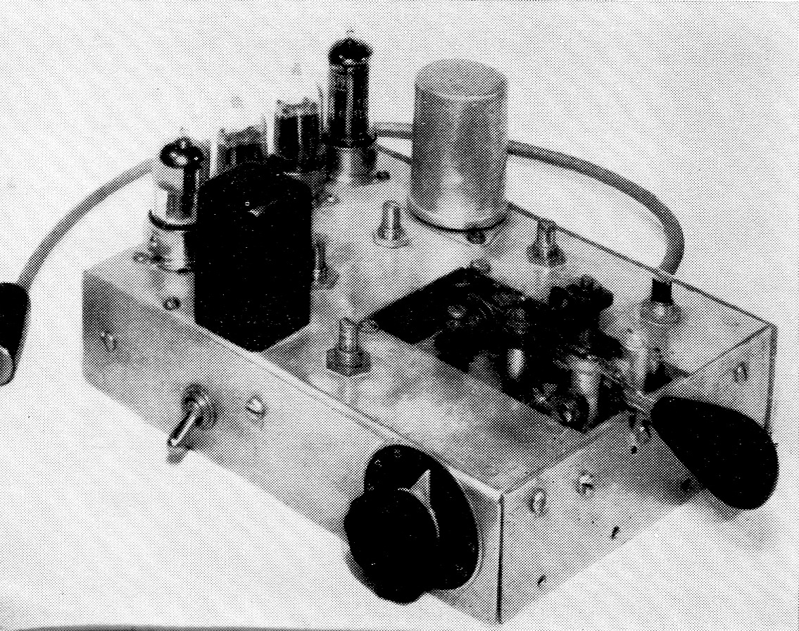
A homemade keying lever is built into the front of W4DFR's multivibrator-type key. The speed control on the side expands and contracts the lengths of dots, dashes and spaces simultaneously. The toggle switch adapts the unit to cathode or grid block keying circuits. Left to right along the back of the chassis are 12AU7s V1 and V2 used for the multivibrator and audio oscillator stages, the 12AX7 sidetone keyer and amplifier, and the 6CL6 keyer tube. The black can is the audio transformer used in the oscillator, and opposite it is the 10-µf. filter capacitor. The shafts between them belong to the tone control and the keyer bias adjustment. The sidetone gain control is to the left of the keying lever, and the dash-space and dot-dash ratio controls are on the right.
As shown in the schematic diagram of Fig. 1, two triode sections of two 12AU7As, V1 and V2n, are used for the multivibrator. While the keying lever is in its neutral position, the cathode lead of Vi is open, and V. draws current heavily. This causes the voltage at the plate of V2A to drop to a low value. (Cathode resistor R9 was made just sufficiently large to self-bias the tube and prevent a ragged audio oscillation from occuring. With no excitation coming from V1, this condition will continue as long as the paddle is in the neutral position. The resistance network, consisting of R10, R11, R12, R13, R14, is adjusted to put a negative voltage greater than cutoff on the grid of the 6CL6 keyer tube V3. Thus V3 looks like an open circuit to whatever is connected across it.
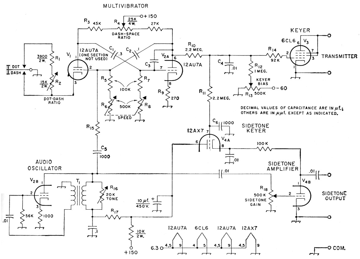
Fig. 1. Schematic diagram of the multivibrator key. Unless otherwise indicated, resistors are 1/2-waft composition; capacitor with polarity marked is electrolytic, others are disk ceramic.
| C1 | 0.3 µF (three 0.1 µF disk ceramics in parallel). |
| C2 | 0.1 µF disk ceramic. |
| C3 | About 6n8 (see text). |
| C4 | 10 nF disk ceramic. |
| C5,C6 | 1 nF disk ceramic. |
| R1 | 3k9, 2 watt. |
| R2 | 15 kΩ, 2 watt control, wire-wound. |
| R3 | 43 kΩ, ½ watt. |
| R4 | 25 kΩ 4 watt control, wire-wound. |
| R5,R7 | 100 kΩ, ½ watt. |
| R6,R8 | 500 kΩ, dual control (CTS-IRC 11-133 PQ control and M multisection). |
| R9 | 270 ohm, ½ watt. |
| R10,R11 | 2M2, ½ watt. |
| R12 | 1 MΩ, ½ watt. |
| R13,R18 | 500 kΩ control. |
| R14 | 92 kΩ, ½ watt. |
| R15 | About 68 kΩ, ½ watt (see text). |
| R16 | 20 kΩ control. |
| R17 | 10 - 56 kΩ ohm, ½ watt (see text). |
| T1 | 3:1 audio transformer (Triad A31 X or similar). |
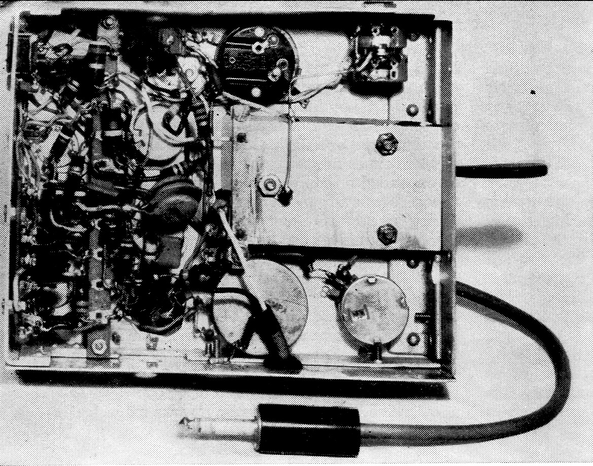
Bottom view of the keyer. The dual-potentiometer speed control is in the upper right corner, and the other adjustments can be identified from their positions in the top view. The aluminum plate on the right is the bottom of the keying lever assembly. The keying lead comes out the lower side of the chassis near the center. On the back side (to the left) are a power connector and a miniature jack for the sidetone output.
Operating the key reverses the picture. When the paddle closes the cathode circuit of V1, plate current flows and the voltage at the plate of Vl is reduced because of the drop across R3. The voltage across coupling capacitor C3 cannot change instantaneously, so the voltage at the grid of V2A goes negative by the same amount as the drop in plate voltage at V1. In other words, C1 charges up very quickly through R3, R4, the power-supply impedance, R9 and the cathode-togrid impedance of V2. This charge causes a negative voltage greater than cutoff to appear at the grid of V2A. When V2A is cut off, its plate voltage rises suddenly and a portion of the increase feeds through resistors R10 and R14 to the grid of V3. The latter will then draw current heavily if its plate and cathode are connected to a d.c. source of proper polarity. This condition is found at the key jack of cathode keying circuits as explained later. With a slight modification, V3 will also control grid-block keying circuits.
V2A will not remain cut off indefinitely. As soon as the charge on C1 drains off through R7, R8 and the resistance of V1 so that the grid voltage of V1A reaches cutoff, V2A begins to conduct. Its plate voltage then drops, and V1 is cut off in turn by the voltage put across C2. As long as the paddle keeps the cathode circuit of V1 closed, V1 and V2A will switch back and forth automatically. The interval when V1 is cut off (space) is determined mainly by C2 and R5R6. The length of a dash tone (V1 cathode grounded, V2A cut off) is set by C3 and R7R8. Since R5R6 always equals R7R8, and C1 = 3 × C2, a dash will be three times as long as a space. R4 provides a fine adjustment of this ratio and serves to balance the currents drawn by V3 and V2A. When the paddle is thrown to the dot post, R1 and R2 are added to the cathode circuit of Vl. The self-bias they provide limits the plate current, and when V1 begins to conduct, its plate voltage and the grid voltage of V2A drop less than before. VIA is cut off for a shorter period forming a dot tone, and the relative length of this tone can be set by R2.
Ganged potentiometers R6 and R8 become the sole adjustment necessary for speeding up or slowing down the dots, dashes and spaces. R6 and R8 should have the same taper although it does not matter what taper is used. The speed control actually works from about 8 w.p.m. to as fast as anyone can manipulate the key. Please do not turn it loose on me.
V1 and V2A generate a wave shape that is close to a square wave, and a small capacitor, C3, is used to suppress a transient click that occurs at the end of a tone. The smallest value that will prove satisfactory here is the most desirable because it does have some effect on the timing ratios. Further shaping of the keying characteristic is done at the grid of the keyer tube. A large capacitor at C4 makes for soft keying, while a smaller one makes sharper characters.
Another 12AU7A section, V2B, was used for the stabilizing audio oscillator in one of the oldest circuits, the simple feedback. Low plate voltage is required for smooth operation as the feedback is very high, and the power supply should be thoroughly decoupled and filtered. Regeneration and also tone can be controlled by the variable resistor R16. The exact frequency is immaterial, and any tone between 200 and 2000 c.p.s. that pleases the ear can be used. A small portion of the generated audio is fed to the grid of Vi through C9 and R15 to synchronize the multivibrator.
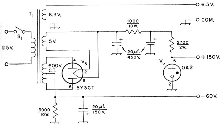
Fig. 2. Schematic diagram of a power supply suitable for the keyer. Capacitors are electrolytic.
| S1 | S.p.s.t. toggle switch. |
| T1 | Power transformer: 600 volt center-tapped, 50 mA; 6.3 volt, 2 A; 5 volt, 2 A (Triad R-7A). |
The other use of the audio is for the side tone. We could see no use wasting a good tone when a facsimile was needed for monitoring, but using it proved to be quite an accomplishment. A circuit had to be used that would not only follow the operation of the keyer tube but also not affect it in any way. One experimental circuit worked beautifully until it was tried-on the exciter. A nice modulated tone was found on the signal output. The solution was again the use of a very old circuit trick, keying the power supply to a small amplifier. One section of a 12AX7 tube, VIA, was rigged up as an electronic keyer in the plate lead of Vie, which is a sidetone "amplifier." The latter stage is not necessary to increase the volume (actually, it operates at a loss), but it is necessary to isolate and follow the keyer, V3. C6 is to prevent any possible reaction on the grid of V3. A small value should be used here or the facsimile will not be exactly the same as the actual transmitted signal. Also, certain values will cause the sidetone output to ring.
The power supply diagramed in Fig. 2 is a conventional 40 mA regulated job, except that a resistor is included in the center-tap lead to provide about 60 volt of negative bias. Of course, power may be obtained from the utility sockets on a receiver or transmitter if the correct voltages are available.
Connecting the keyer.
Do not expect to plug this keyer into any old keying jack and get good results. Ordinary mechanical keys are not selective as to polarity and offer almost zero resistance to the flow of current. Keyer tubes, on the other hand, will carry current in one direction only, and they do have some resistance which must be taken into account. Since the keyer tube must carry sufficient current to satisfy the circuit that is being keyed, heavy duty may require the use of several such tubes in parallel.
When using this unit with a cathode keying circuit, the grid return of the keyed tube in the transmitter must be connected to the key jack tip. If there is a meter in this circuit, it should be included also, as shown in Fig. 3B. This prevents the transmitter tube from developing selfbias due to the internal resistance of V3. If the grid is returned as suggested, the keyer tube offers only a small load in series with the power supply, as would a resistor of equal value placed in the plate-supply lead. The designers of commercial gear have not considered the use of a keyer tube at the key jack and they usually make the grid return to the nearest convenient ground point. Of course, the keyer can be used to operate a d.c. relay of rather high current capacity if it is desired to do so. The keying characteristics are then no longer applied directly to the transmitter, and suitable click and splatter filters would have to be inserted as with a regular mechanical key. The automatic operation would, of course, be retained.
In conventional grid-block keying, the negative blocking voltage is reduced to zero by shorting it to ground with a mechanical key. This allows the normal grid leak or fixed bias to remain operative. The same condition exists if we allow a positive voltage to neutralize the negative voltage. By placing a positive voltage on the plate of keyer tube V3 and connecting the cathode of V3 to the grid block junction through a resistor, we are able to key the transmitter. Connection is made through the regular key jack. This arrangement is shown with a typical 807 buffer or amplifier stage in Fig. 4A. The keyer power supply described provides enough negative bias to cut off V3 and key the 807 even with the 100K resistor and blocking bias in the cathode circuit. The circuit of Fig. 4B should be used if the negative blocking voltage is 100 volts or more. The diode tube reduces the negative voltage from the blocking system which appears at the cathode of V3 during spaces but does not prevent the flow of positive pulses when V3 is actuated. In case you want to use this keyer with both cathode and gridblock keyed transmitters, a d.p.d.t. switch can be added to switch the plate of V3 from key lead to B + and the cathode of V3 from ground to the 27K resistor.
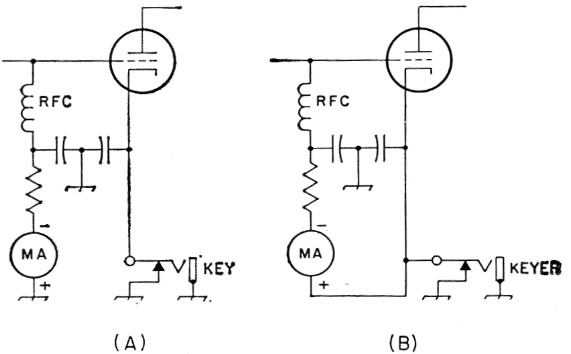
Fig. 3. (A) Conventional circuit for cathode keying. (B) Modified circuit for use with electronic keyer. The grid return is made through the key jack so that the voltage drop across the keyer will not add to the grid bias of the keyed stage.
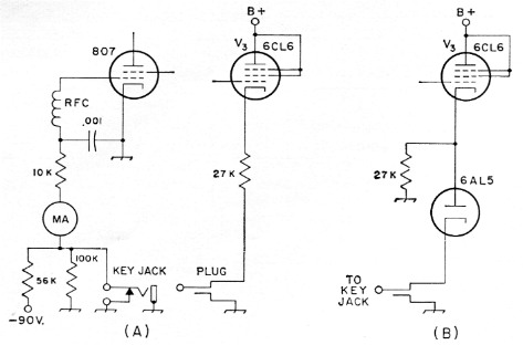
Fig. 4. (A) Diagram showing how the keyer can be used for grid-block keying a typical 807 final amplifier or buffer stage. A positive voltage applied through V3 and the 27,000-ohm resistor neutralizes the negative blocking voltage and has the same effect as shorting it to ground with a mechanical key.
(B) With higher blocking voltages it is necessary to use a diode tube in the keying lead. This reduces the negative voltage appearing at the cathode of the keyer.
The output of the sidetone monitor may be connected to almost any audio amplifier. Some commercial receivers have a "phono" jack which can be used. Since the monitor output is high impedance, there is no deleterious reaction if this is fed directly to the grid of the first audio amplifier in the receiver with shielded wire. It is a general thing to have the audio amplifier portion of the receiver alive even though the front end is muted during transmissions. Problems like this are left to the constructor.
Construction and adjustment
The keyer shown was built on a homemade 5½ × 7½ × 1½ inch chassis, but any standard chassis of about this size can be used. If the keying paddle is to be separate, you can reduce the size somewhat, and if the power supply is built in, you will need a larger chassis. I constructed my own keying paddle, but no claims are made as to its being better than a manufactured one. A modified bug is probably the quickest and cheapest way out if you have one. If the key is mounted on the chassis as shown, it will be necessary to cut an opening and submount it to get the proper operating height. If the key is remote, a double-circuit jack will take care of the problem.
The four tubes are arranged in a line down the back of the chassis, as shown in the photos. The positions of the variable resistors can be arranged to suit the taste of the constructor. Since there are no r.f. or high-frequency audio signals involved, wiring can be cabled and dressed to one's pet desires. Some may feel that there is an abundance of variable controls that could be replaced by fixed resistors. They do simplify initial adjustment, however, and are very handy for trimming up the action of the keyer after a tube replacement. Parts for the keyer should be of good quality but need not be of the precision type. Beware of bargain-variety paper capacitors, especially in the multivibrator circuit, since they may not hold a charge. General-purpose disk ceramics are good in this respect and occupy little space.
The first section of the key to get working is the audio oscillator. Apply heater and plate voltages and adjust R16 and the value of R17 for smooth operation at the desired frequency. Proper polarization of the audio transformer is important, so if the stage does not oscillate, reverse the connections to one winding of T1.
Now connect the sidetone output to an audio, amplifier and apply plate voltage to the remaining stages. With the keying lever closed, adjust R13 and R15 until a series of dots and dashes is heard. Adjustment of the multivibrator requires little effort but only an understanding of what one is trying to do. Just remember that a dash should be three times as long as either a dot or a space. Using a slow speed (Rs and Rs at maximum resistance) it is fairly simple to set the ratio adjustments, R2 and R4, with the aid of a metronome or sweep second hand. Once this has been accomplished, the speed control will compress and expand all the lengths simultaneously.
To synchronize the multivibrator, connect a variable resistor of about 1-megohm maximum at R15. Adjust this resistor until the multivibrator runs about 20 per cent faster than it did with an open circuit at R15. That is, it should make about five dots or dashes in the time it formerly made four. There will also be a slight change in ratio which can be corrected. Disconnect and measure the value of the variable resistor, and replace it with a ½-watt fixed resistor of similar value. Now the keyer should be ready for business.
If keying is to be done in a cathode circuit, connect V3 across the key jack after having changed the grid return as described above. With the keying lever open, set R13 so that V3 is cut off and no current flows to the keyed stage of the transmitter. Care should be taken not to operate the keyer tube too close to cutoff bias since it can become an effective modulator under these conditions. On the other hand, bias that is too negative may produce bad key clicks. Once the correct setting is established, no further adjustment is necessary. Capacitors C3 and C4 will also affect the keying characteristics as mentioned above, and they can be varied to suit the taste of the constructor and the circuit with which the key is used.
Grid-block keying requires a different adjustment procedure. The plate voltage applied to V3 must be set to allow the keyed stage to draw normal grid current by the following method: First, adjust R13 in the keyer until a sidetone is heard strongly from the monitor. Hook a temporary voltage divider resistor between B + and ground, and connect the slider to the plate of V3.
Start with the slider near the grounded end and increase the plate voltage until the grid of the keyed stage draws normal current with excitation applied. Then increase the bias on V3 by turning R13 until the sidetone stops and the keyed stage blocks. Normal operation with the keying lever is now possible. The temporary voltage divider can be replaced with suitable fixed resistors or with a voltage source of the correct value.
No further shaping should be necessary, but make the r.f. bypass in the grid circuit of the keyed stage of the transmitter as small as possible. Excessive bypassing will make the keying too soft. Sharpening of the characters can be accomplished by using lower values for R10 and R12 to load both the negative and positive supplies more heavily.
Operating the finished key is about as simple as a semiautomatic mechanical key. One only has to let the automatic features do the work of making both dots and dashes. There are no weights or screws to adjust for different speeds; merely turn one knob.
Dr. Roy R. Campbell, W4DFR.