A simple antenna system for the novice
Using random-length, end-fed wires.
An antenna that gets wide use on the lower frequency frequency bands, particularly with newcomers, is a random length of wire. The customary procedure is to have one end of the wire connected directly to the output terminal of the transmitter and the other end supported by a tree or mast. (Users of such antennas often refer to their antennas as "long" wires, although a long wire, as considered in connection with directive systems, is usually several wavelengths long at the operating frequency.) As with any antenna, there are certain problems one is likely to encounter in getting the system to work. In this article the random-length antenna will be discussed.
How long an antenna?
If the correct coupling methods are used between the transmitter and antenna, a wire that is quite short for the frequency can be made to work, although it is generally true that the shorter the antenna for a given frequency, the poorer its over-all performance. It is customary procedure to recommend antenna lengths no shorter than one-quarter wavelength for the frequency in use. However, shorter lengths will work and produce contacts.
For example, on 75 meter a quarter wavelength is about 60 feet long. Amateurs who operate 80 meter mobile usually have an 8 foot long whip for the antenna. A few years ago, W1BDI, the ARRL Communications Manager, operated 80 meter c.w. from his car on a trip around the country. Using 25 watts input and a short whip antenna, he managed to maintain a daily-schedule with Headquarters from distances well over 2000 miles away. This example is mentioned to show the amateur with restricted antenna space that 80 and 40 meter operation is possible using very short antennas.
Nevertheless, assuming that multiband operation is planned with 80 meter as the lowest band, try to make your antenna at least 65 feet long. There are two general rules you can follow with this type of antenna - make it as long as possible and get it as high above ground as you possibly can. If you don't have a straight run of at least 65 feet, it is possible to bend the antenna to make up the difference. In other words, part of the antenna can be run at right angles in order to increase the over-all length. If you find it impossible to get a 65 foot run then make the antenna just as long as you can. The shorter antennas, while not having as good performance, will produce plenty of contacts.
Shown in Fig. 1 are a couple of examples of typical installations. For example, if your shack is in the cellar or first floor, you can run the wire out the window, up to the eaves, and then out to the mast or support. If your mast supporting the far end of the antenna is high enough, you can bring a portion of the antenna back down toward ground to increase the overall length.
There is no way to predict in advance what the pattern of your antenna will be. The simplest approach is to put it up and try it. You'll soon discover which directions are best by the reports you receive. By all means, don't be afraid to experiment with different antenna layouts. You might be pleasantly surprised by the results.
What materials to use
Practically any kind of antenna wire can be used, either copper or aluminum, bare or insulated. However, No. 12 or 14 copper, copper-weld, or "copper-clad" is preferable. The antenna wire should, of course, be insulated wherever it goes through a wall or window and where it is supported. Flexible plastic tubing, available at any parts distributor, can be slipped over the wire at windows or through walls. Ordinary dime-store glass insulators can be used as end or support insulators.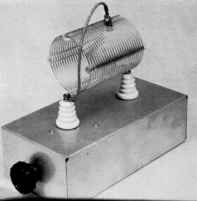
The knob on the front of the chassis is the control for CI. The clip lead, which is 9 inches long, is connected to the input end of the coil An E. F. Johnson type LC8 is used for the clip. Feed-through insulators are used to hold the coil in place. A clip on the antenna lead can be used for connecting the antenna to the output end of the coil.
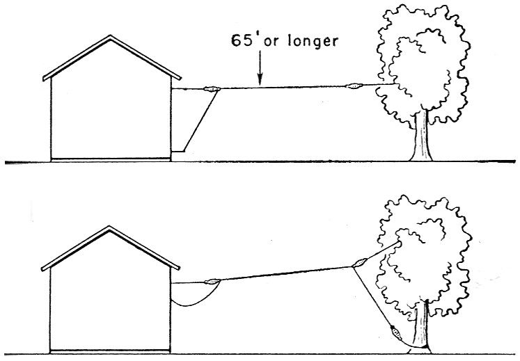
Fig. 1. These drawings demonstrate a couple of different methods for installing the antenna. As mentioned in the text, try to get the antenna as high as possible above ground.
Some amateurs who have landlord problems use a very fine wire, No. 30 or smaller, because the wire is practically invisible when it is up in the air. With fine wire, rubber bands can be used for supports and insulators. If you happen to be in such a situation it is worth while to consider such an installation. (You'll probably have to make the installation after dark, so don't lose the wire putting it up!)
Coupling the antenna to the transmitter
In many instances the end of the antenna can be connected directly to the antenna terminal on the transmitter. Most transmitters these days have a pi-network tank circuit which is capable of coupling over a wide range of values. There is no simple method of determining what the end of the antenna "looks like" to the transmitter. Depending on the band and frequency, the impedance at the end of the antenna will range from a few ohms to several thousand. For this reason a wide-range coupling circuit is needed at the transmitter, otherwise the transmitter will not load. Your instruction book for the transmitter should tell you what values the pi network will work into. While not in the Novice class, it should be pointed out that there are a few commercial rigs that will only work into a 50 ohm load. Only in rare instances will this type of antenna work out to be 50 ohm impedance. For this reason a coupling or matching circuit should be installed between the rig and antenna.
The coupler
Shown in Fig. 2 is the circuit of a simple antenna coupler. The circuit consists of a coil, L1, and a variable capacitor, Cl. In order to have the right amount of inductance for any band the coil is provided with a shorting clip which is used to short out turns on the coil. The unit shown in the photograph was mounted on a 3 × 5 × 10 inch chassis. There is nothing critical about the construction; in fact, the whole unit can be mounted "bread-board" style if desired.
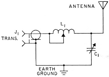
Fig. 2. Circuit diagram of the simple antenna coupler.
| C1 | 140 pF variable (Hammarlund MC-140-S, E. F. Johnson 140R12, or equivalent). |
| J1 | Coax chassis receptacle, SO-239. |
| L1 | 24 turns No. 12, 6 turns per inch, 3 inch diameter (Air Dux 2406). |
The coupler should be connected to the transmitter via a length of coax line; either 50 or 70 ohm line will be suitable. The length of coax used will, of course, depend on where you mount the coupler. Some hams prefer to have their couplers mounted near where the antenna enters the shack and others want it near the transmitter. The latter position makes for easier adjustments.
If you have an s.w.r. bridge such as the Monimatch(1) or a similar type, it should be installed in the coax line. The use of an s.w.r. bridge is recommended because it will show you when the coupler is correctly adjusted and also serve as an output indicator. If you don't have a bridge, then you can use an output indicator such as a flashlight lamp in the antenna lead or a neon bulb touched to the end of the antenna.
Note in Fig. 2 that the coupler is connected to an external ground. (This is in addition to the ground connection that always should be made to the transmitter itself. See the Stray on page 69 of this issue.) This can be a water pipe or a connection to a ground rod driven in the earth. The setup will work without the ground connection, but you'll probably get better results if you use one. The thing to do is to try the coupler both ways.
Adjustment procedure
Connect the end of the antenna to the coupler at the junction of C,L1 as shown in the circuit diagram. If you are using enamel-covered antenna wire be sure to scrape off the enamel! Let's suppose you are starting off on 80 meters. Turn on the rig and resonate the final amplifier for a dip in the plate-meter reading. If you are using an s.w.r. bridge, switch the bridge meter to read reflected power and then adjust C1, looking for a dip in the bridge meter. Unless you are very lucky you probably won't get an indication because the coil tap won't be at the correct spot. Start at one end of the coil and short out one turn at a time. Continue adjusting C1 until you reach a point where the bridge meter starts to dip or "null." Retune the amplifier tank circuit to resonance each time you adjust C1 or the tap.
Once you get close to the correct tap point you'll probably have to move the tap a fraction of a turn at a time in order to get a complete null on the bridge meter. When you find the correct tap point, switch the bridge meter to read forward power. Next, adjust the transmitter loading control to bring your plate current up to whatever full loading is supposed to be. Don't change the settings of the tap or C1 because once you have the coupler adjusted for a null as indicated by the bridge meter, the coupler is correctly adjusted for the frequency you are using. You can use the forward power reading of the bridge meter to help you adjust the transmitter tank capacitor and the loading control. Tune the transmitter controls for maximum power output as indicated by the bridge meter while keeping the plate current reading to whatever limits are required for the transmitter in use.
If you are using an output indicator instead of a bridge, keep adjusting C1 and the tap until you get an indication of power output. Be sure to resonate the plate circuit of the transmitter for a plate meter dip as you make each adjustment of C1 and the tap. The idea here is to get the maximum power output for a given plate current reading. When you have such a condition the coupler will be adjusted correctly.
Make a note of the settings of C1 and the tap position and then proceed to the next band. Keeping a record of the settings will make it that much easier when you want to switch bands. The same adjustment methods outlined above should be used on the other bands.
Notes
Lewis G. McCoy, W1ICP.