A novice t.r. switch
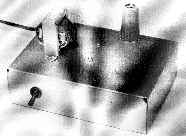
This photograph shows the completed unit. The only components mounted on the top of the chassis are T1 and the 6AH6. At the left front is S1.
More operating convenience for your station.
During last Field Day the writer had occasion to use a transmitter with a built-in t.r. switch that was designed by Ed Hart, W2ZVW. Never having used a t.r. switch to any great extent, it was interesting to note how smoothly this particular unit worked. What was of even greater interest was the simplicity of the t.r. circuit. Here was something any Novice could build, didn't cost much, and would simplify the operating controls of his station.
How the t.r. switch works
It is always to the amateur's advantage to use the same antenna for both transmitting and receiving. Many amateurs accomplish this with switches or antenna change-over relays. This, in turn, calls for a manually-operated switch which actuates the relay when going from transmit to receive. A t.r. switch is an electronically-operated device requiring no manual operation.
Fig. 2 shows how the t.r. switch is used in two types of installations. One method shows how the unit is installed in a system where an antenna coupler is used. The other setup shows the installation of the t.r. switch where coax is used directly between the transmitter and antenna. Now look at Fig. 1, the circuit of the t.r. switch.
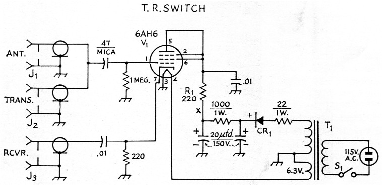
Fig. 1. Circuit diagram of the t.r. switch. Unless otherwise indicated, decimal values of capacitance are in µF, others are in pF, resistances are in ohm, resistors are ½ watt. Capacitors marked with polarity are electrolytic.
| CR1 | Selenium rectifier, 50 mA (Sarkes-Tarzian Model 50). |
| J1,J2,J3 | Coax chassis receptacles, or phono jacks. |
| R1 | 220 ohm. |
| S1 | S.p.s.t. toggle. |
| T1 | Power transformer, 125 volt, 15 mA, 6.3 volt, 0.6 A. (Stancor PS-8415, Knight 61 G410). |
The operation goes like this: When the transmitter key is closed, a signal is sent out along the coax line. Attached to the line is the t.r. switch. A portion of the r.f. voltage appearing on the line drives the 6AH6 grid positive. The rectified voltage then biases the 6AH6 so very little power is fed to the receiver. When the key is opened, any signal coming down the line from the antenna is not strong enough to cause bias to be developed. The 6AH6 then acts as a cathode follower feeding the signal into the receiver. A cathode follower, while not having any gain, does have a broad-band characteristic in its output circuit which is ideal for this application.
Construction details
The unit shown in the photographs was built on a 2 × 5 × 7 inch chassis. The t.r. switch described here has its own power supply. However, many receivers and transmitters have power takeoffs, and if yours does, the cost of the t.r. switch can be lessened by eliminating the power supply. Power requirements for the 6AH6 are approximately 100 volt d.c. at about 10 mA and 6.3 volt at 0.45 A.
If you decide to use an external power source, the plate voltage should be fed into the 6AH6 at the point marked X. The resistor R1 serves the same purpose as an r.f. choke, but is, of course, much cheaper. In connecting an outside power source you'll need three leads, one for the plate voltage or B plus, one for a ground connection, and a lead for the 6.3-volt heater line.
When installing the socket for the 6A116 mount it as close to the terminals J1 and J2 as possible. This is done in order to keep the lead length between J1 and J2 to the grid of the 6AH6 as short as possible. This reduces the chances for stray pickup of r.f. which may tend to "block" the receiver when transmitting. For the same reason, a short length of shielded wire is used between the cathode, Pin 7, and a tie point mounted at J3. The 0.01-1.f. capacitor is connected between the tie point and the terminal of J3, keeping the capacitor leads as short as possible.
Regular coax chassis terminals were used for J1, J2, and J3. However, phono jacks can be used instead, thereby cutting the cost of the unit.
Installing the t.r. Switch
Fig. 2 shows two examples of how the t.r. switch should be installed. There is one important point to keep in mind about the t.r. switch. If the voltage appearing at the grid of the 6A116 is too high there is a danger that the tube can be ruined. For this reason, the standing-wave ratio on the coax line should not be over 2 or 3 to 1 for Novice powers of 75 watts input or less. In any event, it is always a good idea when using a coupler to have an s.w.r. bridge(1) installed in the coax line to show when the coupler is correctly adjusted. The t.r. switch can be used for power inputs up to about 300 watts if the line is well matched.
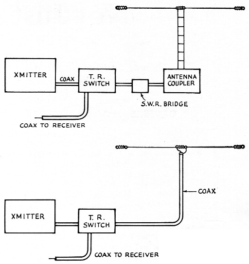
Fig. 2. Two methods of installing the t.r. switch in your station.
If your system has direct coax feed from the transmitter to the antenna, the t.r. switch should be installed close to the transmitter. If you live in an area where TVI is a problem (who doesn't!), a low-pass filter should be installed on the coax line between the t.r. switch and the antenna. Most t.r. switches are harmonic generators and this one is no exception.
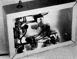
Note that the 6AH6 socket is mounted close to the coax terminals. This is done to keep the lead lengths short. CR1 is the rectangular object at the top center. Just above the rectifier is the dual 20 µF electrolytic capacitor, mostly concealed by the chassis flange in this view.
The t.r. switch described here was tried with three or four different makes of receivers. In no case did the signal pickup block the receiver when the transmitter was keyed. The signal was loud enough so that it was more comfortable listening with the r.f. gain reduced during transmission, particularly if the listening was done on the eame frequency as the transmission. An ideal system would have means for receiver muting whenever the key was closed. However, any such system would be more complex than the simple t.r. switch shown here.
Notes
Lewis G. McCoy, W1ICP.