A brief case portable antenna
Loaded dipoles for 80 through 10 meter.
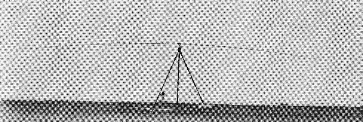
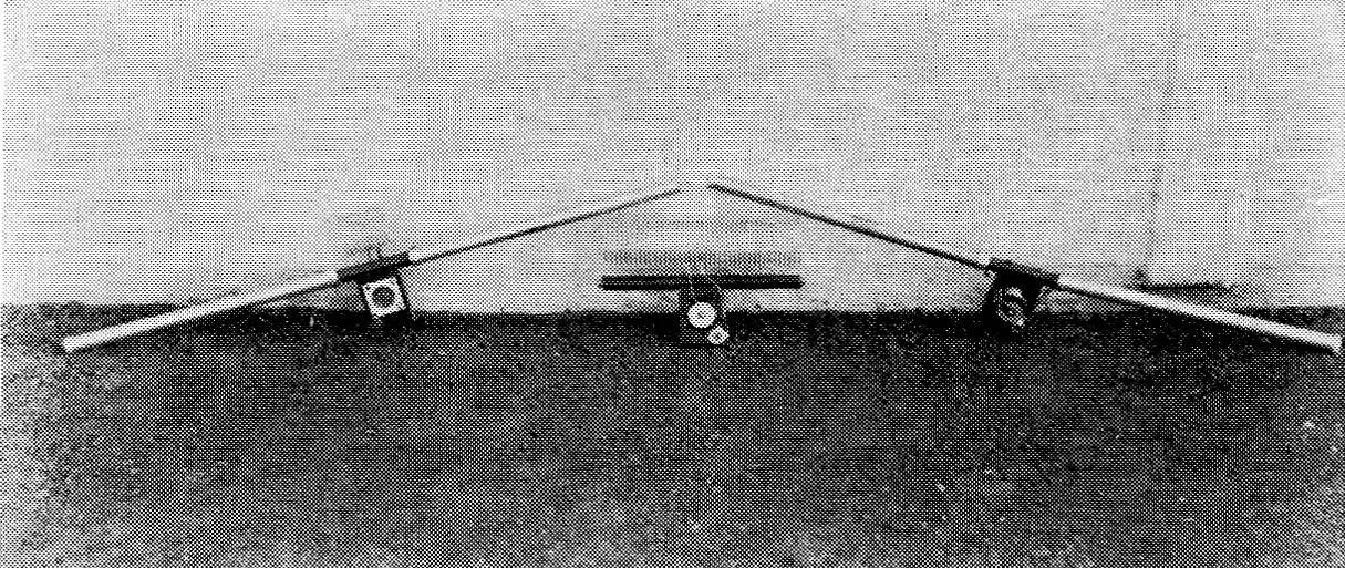
The "Brief-case" portable antenna with sections extended.
Many books and articles have been written on just as many types of antennas for portable use. The answer to the need for a truly portable antenna having wide frequency capabilities and being very small was not found in conventional designs. Although the whip antenna as used in mobile equipment has done a remarkably fine job, it still does not lend itself to truly portable operation such as in hotels, in the rural areas, or in areas where a vehicle is not available. The antenna to be described fills the need for this type of service.
Loss factors
The design for this radiator (see photographs and Fig. 1) does not follow the general pattern. Although a radiator with the center loading inductance was not recommended as being satisfactory, the first model made with an open loading coil proved to be very effective, and steps were taken to dress up the unit by putting on a plastic housing as well as a plug-in mounting for each coil. After construction was completed, accompanied by an increase in eye appeal, the antenna was connected to the same exciter, whereupon an attempt was made to establish contact with other stations. The results were most disappointing. The few stations hearing the signal complained of an extremely weak signal, while others couldn't hear the signal at all. The revision was discarded in favor of the original open design. Tests were carried on with the coil in its original condition to assure us that all was working as well as before. From these experiences it was clear as to what had happened. Loss in efficiency was attributed to the capacitive loading of the enclosure and mounting. It also became evident that the loading coil was the critical component in the system. The loading coil should be free from other objects, either conductors or dielectrics. Loading capacitance from end to end was also important, as was the capacitance between turns. If such an antenna is to function effectively, the ideal condition would indicate the use of a large inductor with wide spacing between turns and as long as possible. This latest bit of information explains why many antennas have not been satisfactory when the loading coils used in short versions of an antenna have been accompanied by external or internal capacitive loading.
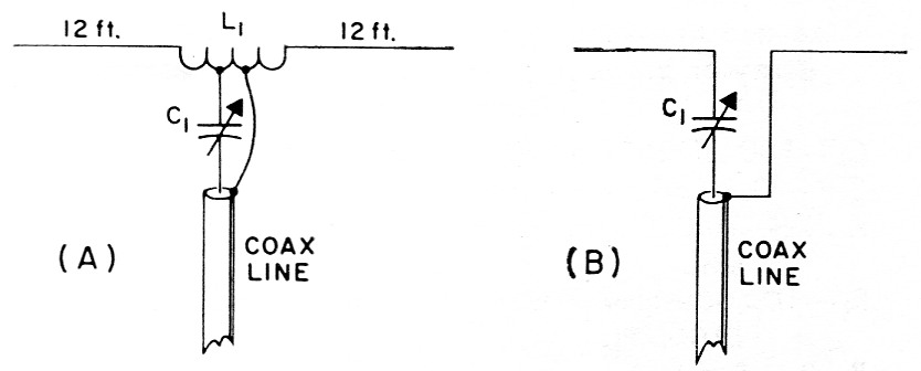
Fig. 1. The loaded arrangement shown at A is used on 80, 40 and 20 meter. The loading coils, L1, for all of these bands are wound with No. 12 or 14 wire, 4 turns per inch. The 80 meter coil has 80 turns, 3 inch in diameter (two full lengths Air Dux type 2404T), the 40 meter coil has 40 turns, 2½ inches in diameter (one full length Air Dux type 2004T), and the 20 meter coil has 10 turns, 2 inch in diamater (Air Dux type 1604T). In all cases, the outer conductor of the 50 ohm coax line is connected to the center of the coil. The capacitor C1 (a 100 pF air or vacuum unit) is tapped on at 8 turns for 80 meter, 4 turns for 40 meter and 2 turns for 20 meter from the center. Loading coils are not used on 10 and 15 meter, the capacitor C1 serving as a matching capacitor.
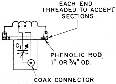
Fig. 2. Sketch showing details of the antenna coupling unit. One of these units is provided for each band, except in the case of 10 and 15 meters, where the coil is omitted and the same unit is used for both bands with the connections shown in Fig. 1B.
Adjustment
In the tuning adjustment, a first requirement is that the antenna be in exact resonance at the transmitter frequency if a low s.w.r. is desired. Also, a small capacitor is used in series with the center conductor of the coax line. As can be noted in the diagram, the shield of the coax is firmly grounded to the center of the inductor, while the center conductor of the coax connects through the series capacitor to a tap on the coil. The position of this tap is not critical and generally two or more turns are employed, depending upon the frequency. The lower frequencies, of course, require more turns than the higher frequencies. The series capacitor is adjusted to bring the s.w.r. to its lowest point. After a few attempts at tuning, the operator will find it simple and fast to make adjustments on any frequency, since tuning procedures are the same for each frequency. It is very common to get minimum readings where the meter will not move on the reflected power side, but will show full power in the forward position.
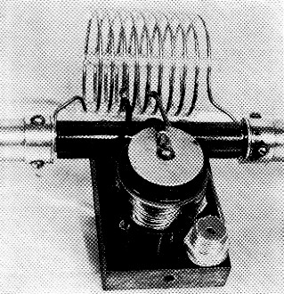
Close-up view of the 20 meter assembly.
Antenna tuning units with and without the telescoping antenna units attached. The units, from left to right, are for 20 meter, 40 meter and 10/15 meter.
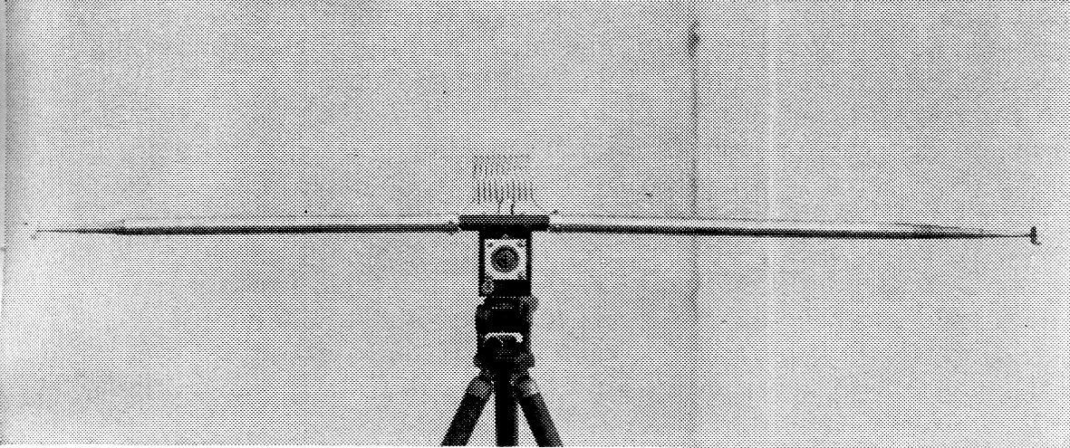
The antenna sections collapse into 15-inch lengths. This view shows the 20-meter tuning unit in place.
Antenna sections and capacitor
The sections of this particular antenna were taken from surplus equipment and bear the designation AN29. They are made of aluminum and collapse down to 15-inch length. Extended they are approximately 12 feet long. Our models use a small adjustable vacuum capacitor known as the GSLA 120 (Jennings), having a maximum capacitance of 120 µµf. For those not having such a capacitor available (and probably no one else does), a small air variable capacitor having a maximum rating of 300 to 400 volts will work r very well in this service. Approximately 80 µµf. is required for tuning. We have examined a collapsible whip antenna made by Kaar Engineering in Palo Alto, which is nuch stronger than the AN29, but considerably heavier. It extends to about 15 feet and is available, we understand, in Palo Alto.
Various insulating materials may be used to support the antenna inductor assembly. In fact, the voltages developed on the higher frequencies are extremely low, but as the frequency decreases the voltage obviously will increase quite rapidly. We have operated these antennas up through 40 meters, and although they will operate on 80, much more care and skill is required in the tune-up. The Q on this frequency becomes much higher and with it a much narrower frequency range is permissible.
Operation
After using a portable antenna inside as well as outside of buildings, and at various locations, with different operators making the adjustment, this method seems to present a practical and interesting approach to portable antennas for those who cannot take the time, or tolerate the weight or space required for conventional jobs. One of the big advantages, of course, is that no ground is required on this system and, should the operator be on top of a building he can, in a few minutes, set up to operate a transmitter and compete with many other stations on the air, with satisfactory results as compared to conventional stationary equipment. It is believed that an antenna could conceivably be used outside of a steel building and produce a curtain effect. Someone may find this out and report later as to results.
It is actually a pleasure to use a brief-case portable. I have worked across the continent as well as to the Islands with a 100 watt exciter.
Jo Emmett Jennings, W6EI.