A combination code-practice oscillator-monitor
Two units for the price of one.
Lewis G. McCoy, W1ICP.
In order to obtain an amateur license one must learn to send and receive the International Morse code. A good way for the newcomer to learn the code is with a code-practice oscillator. The code-practice oscillator described here produces an audio tone similar in sound to the signals one would hear when listening with a communications receiver.
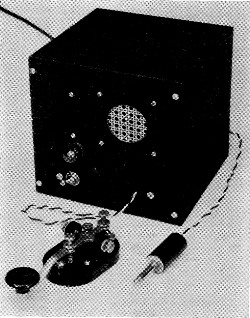
This view shows the completed unit. The switch at the lower left corner is S1. Just above the switch is the neon bulb. The leads coming out of the back connect to P1, which is used when the unit works as a monitor.
After obtaining a license and getting on the air, nearly every amateur working c.w. needs some method of monitoring his "fist" to know that the code characters he makes are correct. This is particularly true of the Novice who wants to increase his speed and send accurate code. Many times the Novice, because of being restricted to crystal-control, must work stations on a different frequency than his own, which makes it difficult to monitor his sending with his receiver. If he tunes to his own frequency there is always the danger of not being able to find the station he is working when the time comes to stand by. The unit to be described here serves the dual purpose of a code-practice oscillator and a monitor which is independent of the receiver. The oscillator has sufficient speaker volume to take care of large code-practice groups such as those sponsored by radio clubs.
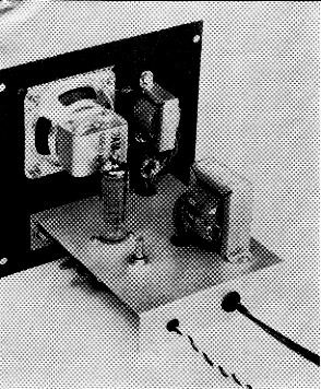
To the right of the speaker is T1, the output transformer. Just below T1 is the neon bulb, supported in a rubber grommet. The power transformer is at the right of the chassis and the 6AQ5 and volume control are on the left.
The circuit
The audio oscillator (that portion of the circuit that makes the tone) consists of R1, R2, V1, and C2 in Fig. 1. When one side of V1, a neon bulb, is connected to ground via the key, the circuit oscillates, producing an audio tone which is coupled to the grid of a 6AQ5 through C1. The signal is amplified in the 6AQ5 and fed to the speaker through T1. R3 serves as a volume control to adjust the loudness of the signal.
When the unit is used as a monitor, P1 is plugged into the key jack of the transmitter. More about this in a moment.
The power supply is a half-wave rectifier circuit with capacitor input. A dual 20 µF electrolytic capacitor, C3, with a 1000 ohm resistor serves as the power-supply filter. Voltage out of filter is approximately 130 volt d.c.
Building the unit
Most of the components are mounted on a 1 × 5_1/8 × 4 inch aluminum chassis (Bud CB-1619). The speaker, output transformer, and neon bulb are mounted on the panel of a 6 X 6 X 6-inch cabinet (Bud CU-1098). Note in the bottom-view photograph that the power-supply components are mounted along one side of the chassis with the oscillator along the other side. There is nothing critical about the placement of the parts, but it is a good idea to follow the general layout shown. The volume control on the unit shown here was mounted on the chassis just to the rear of the 6AQ5. If desired, this control can be mounted on the front panel.
The neon bulb is mounted on the front panel and supported by a 2-inch-diameter rubber grommet. Having the bulb on the panel shows you when the oscillator is working, since the neon bulb blinks on and off as the unit is keyed.
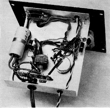
At the left of the chassis in this bottom view is C3, the dual electrolytic capacitor. To its right is CR,. The 6AQ5 socket and volume control are at the right hand side of the chassis.
Using the code-practice oscillator
When the unit is completed, connect a key to the oscillator and try it. If you want a lower-pitched tone you can reduce the value of Rl. Increasing the value raises the pitch. Try a 560 kΩ resistor to lower the pitch, or 820 kΩ to raise it. If your junk box has an extra 1 mΩ control, you can connect it in the circuit in place of R1 and vary the pitch with the control. If you decide you want to put in a pitch control, Fig. 1 shows how it can be done. The control is inserted in the circuit in place of the fixed resistor at the two points marked "X."
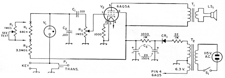
Fig. 1. Circuit diagram of the code-practice oscillator-monitor. All capacitances are in µF, resistances in ohm; unless specified otherwise, resistors are ½ watt.
| C1,C2 | 1 nF disk ceramic. |
| C3 | Dual 20 µF electrolytic, 150 volt. |
| CR1 | Selenium rectifier, 50 mA (Sarkes-Tarzian type 50). |
| LS1 | 2 inch p.m. speaker. |
| R1 | 680 kΩ. |
| R2 | 3.3 MΩ, (Or variable-see text.) |
| R3 | l MΩ control. |
| P1 | Plug, to fit transmitter. |
| T1 | Power transformer, single tube to voice coil, 5000 to 3.2 ohm (Knight 62G064). |
| T2 | Power transformer, 125 volt, 15 mA; 6.3 volt, 0.6 A (Stancor PS8415, Knight 61G410). |
| V1 | Neon bulb, NE-21. |
| V2 | 6AQ5A. |
As a monitor
In order to use the unit as a monitor, plug P1 into the key jack of your transmitter and connect your key to the oscillator key leads. The monitor is designed to he used primarily with cathode-keyed transmitters where one side of the key jack is connected to chassis ground and the other side to the cathodes. Check the circuit diagram of your transmitter to make sure that one side of the key jack is grounded. If it is not, the monitor should not be used in its present form. If the key jack is grounded and your rig uses some other type than cathode keying, you can try the monitor to see if it works. If it doesn't, then a double-pole single-throw relay should be used to key the monitor and transmitter separately. The method for connecting a 6-volt a.c. relay is shown in Fig. 2. One arm of the relay is used to key the monitor and the other arm to key the transmitter.
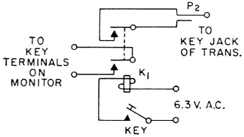
Fig. 2. Circuit showing method of connecting a keying relay to the monitor.
| K1 | Keying relay, double-pole, single-throw, 6 volt a.c. coil (Advance GHA/2C/6VA or equivalent). |