The DL1FK compact multiband beam antenna
The short beam with loaded elements still remains the sole solution for a multitude of hams who want a directive antenna for DX work without exceeding restrictions on space or violating aesthetic sensibilities. This one is light yet rugged, and employs a unique method of band shifting.
For the average amateur, the assembly of a full_size rotary beam for the high-frequency bands presents problems that are not easily solved. Even when suitable space is available, and there are no other restrictions to circumvent, there is a natural inertia to overcome because of the mechanical difficulties and expense involved. This is true especially if it is necessary to put up a separate antenna for each band. It is therefore quite understandable that there has been much interest in the various forms of single compact beam antennas capable of three-band operation. Antennas of this type, usually being full-size for 10 and 15 meters, have given very good results on these bands, and any disadvantages that may be inherent in some types of "short" beams when operated on 20 meters have not been too apparent during the now-ending period of increasing and decreasing sunspot maximum.
The author has tried many of the suggested designs of the so-called miniature triband beam, and has thoroughly examined their respective advantages and disadvantages. The upshot of all this investigation has been the development of a new-style three-band beam which does much to eliminate electrical drawbacks of, and improve the performance over, some other constructions. In addition, much thought has been given to the mechanical design with the result that such a three-band beam antenna can be made light enough to be easily handled, and turned readily by a small TV rotator. Yet it is strong enough to resist the onslaught of weather that has persistently caused damage to other heavier designs so that they had to be given up.
The driven element
The electrical design is shown in Fig. 1. The physical length of the driven element (A) is approximately ½ wavelength for 15 meter. End loading is used for 20 meter in preference to center loading so that the resistance of the loading inductor will not be at a high-current point. On 10 meter, the driven element operates as two half waves in phase with a theoretical gain of possibly 2 db. over a half-wave element. On 15 meters, the two sections also operate in phase, but since they are less than one-half wavelength long, the gain over a dipole will be slight. While some matching system might be devised for feeding the driven element with low-impedance coaxial line, the use of a tuned open-wire line is by far the simplest, and losses are minimized.
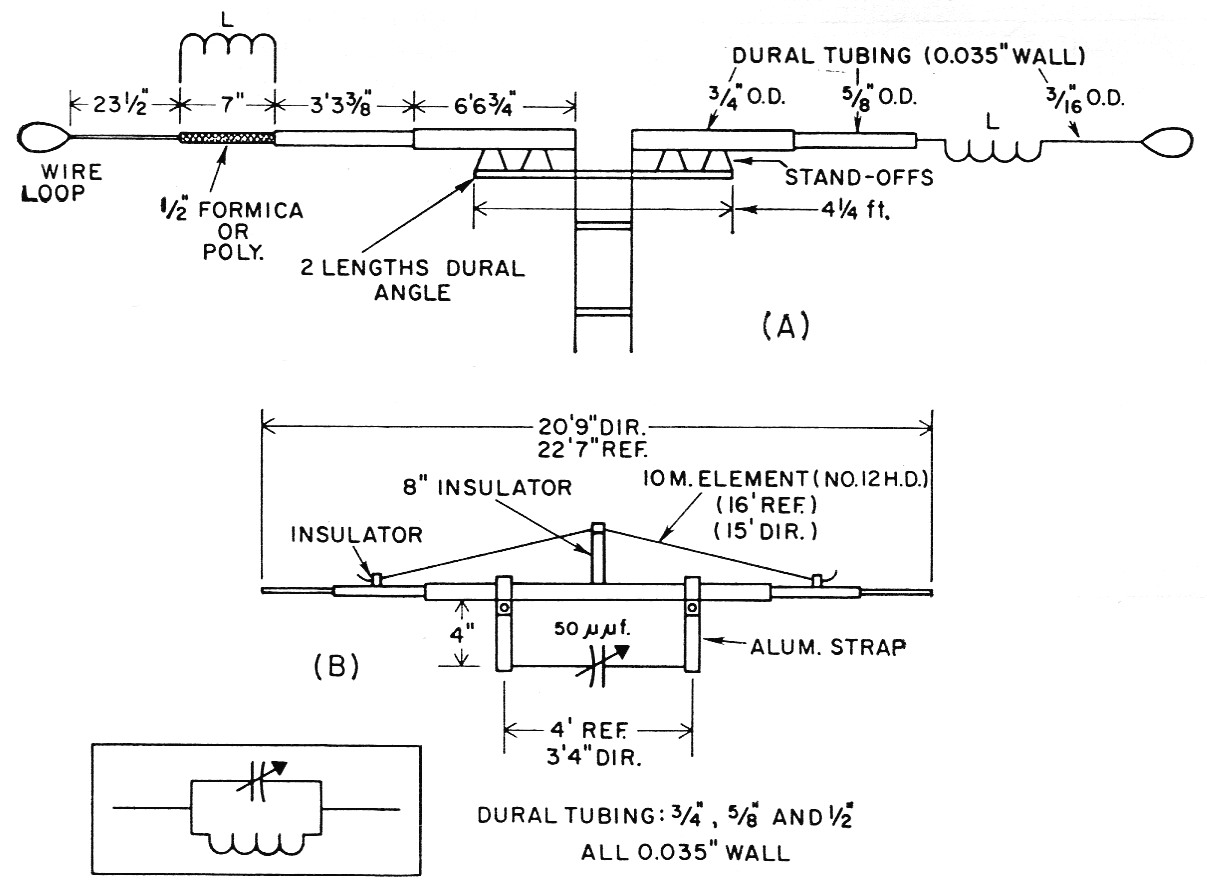
Fig. 1. Sketch showing details of the driven element (A) and parasitic elements (B) of the DL1FK 3 band beam antenna.
The equivalent of the 15/20-meter parasitic elements is shown at the lower left. Wire loops at the ends of the driven element are approximately 4 inches long.
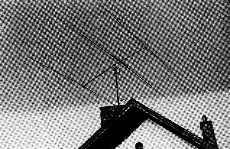
DL1FK's 3 band compact beam may be easily roofmounted by one man. A short section of slack feed line between the feed point and an anchor on the most permits rotation.
Parasitic elements
A unique part of the design lies in the parsitic elements, Fig. 1B.(1) The physical lengths of these elements are also approximately those suitable for director and reflector for 15 meters. On 20 meters, the capacitor and the loop formed by the center section of the antenna, and the capacitor connecting leads comprise a tuned circuit on which the end sections are tapped. The end sections being less than one-half wavelength long present a capacitive reactance as viewed by the tuned circuit. This reactance is nullified by adjustment of the capacitor which tunes the combination to resonance at 14 Mc.
On 15 meter, this tuned circuit will have a net capacitive reactance, shortening the electrical length of the element. To compensate for this, the physical length is extended as necessary over that normally used for 15 meter.
Separate parasitic elements are used for 10 meters. These also serve as mechanical bracing for the lower-frequency elements, as shown in Fig. 2B.
The element spacing is a compromise - 5 feet for the directors and 8 feet for the reflectors. This results in director spacings of approximately 0.14, 0.1 and 0.07 wavelength, and reflector spacings of 0.23, 0.17 and 0.12, respectively, for 10, 15 and 20 meter.
Construction
Essential dimensions are given in Fig. 1. The hin-wall tubing used for the elements has a tendency to yield in the face of a strong wind and, although the swaying and shaking of the elements in severe gusts looks dangerous, I have had no trouble with breakage of the elements or damage to the gears of the rotator. In cutting the tubing sections to length, an allowance of several inches should be made for telescoping at the joints. At each joint, the tubing should be slit lengthwise for a short distance, and the joint made secure with a clamp. The coils L each have 6 self-supporting turns of No. 12 wire, 1 inches in diameter, turns spaced out to a coil length of 4 inches. The element is broken by a short section of insulating rod at the points where the coils are inserted.
The boom is 13½ feet long and consists of two parallel lengths of 1-inch dural tubing spaced 5 or 6 inches. Clamps, such as shown in Fig. 2A, may be used every foot or so to maintain the spacing and provide cross bracing. As an alternative, the members might be bolted together with spacers between.
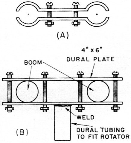
Fig. 2. Sketches showing a boom-spacing clamp (A) and arrangement for mounting the boom on the rotator (B).
The boom is attached to the rotator by clamping it between a pair of rectangular dural plates, as shown in Fig. 2B. A short length of tubing that will fit the rotator socket is welded to one plate.
When using a light rotator, it is important that the rotator be mounted at the top of the supporting mast with only the short stub of Fig. 2B between the rotator and the antenna. Any slight vertical force at the ends of the boom arrives at the bearings of the rotator greatly magnified through lever action which increases as the distance between the rotator and the boom is made greater.
The position of the mounting on the boom should be adjusted to distribute the weights evenly on the two sides. The weight of the length of transmission line necessary to cover the distance between the feed point and the mast, with allowance for slack, should be included. The parasitic elements may be bolted or clamped directly to the boom, making sure that this is done at the exact center of the element. The mounting for the driven element is attached to the boom in the same manner.
The tuning capacitors for the parasitic elements should be enclosed in weather-tight plastic boxes attached to the boom. The connections between the capacitors and the clamps are made of antenna wire.
10 meter elements
The 10 meter parasitic elements are made longer than needed at first. Anchor one end at one of the insulators with several inches of wire extending beyond the insulator. Run the other end of the element wire through or around the insulator and bring enough tension to bear so that all sag disappears when the element is balanced at the center. The excess length of wire beyond the insulator may be snipped off a little at a time (or rolled up) as necessary to tune the element.
The complete assembly, including rotator and a short roof-type mast, can easily be handled by one man.
Transmission line
Although the lower losses of open-wire transmission line as compared to coax, even when the coax line is matched, are well recognized, many constructors prefer to use coax cable because of the mechanical difficulties involved in applying open-wire line to a rotating beam antenna. The author made his own open-wire line of flexible antenna wire, as shown in Fig. 3. Between spacers, which are about 12 inch apart, the wire is covered with 4 inch insulating sleeving. The spacers are drilled for the wire and no fastening to the wire is necessary, since the tubing keeps the spacers in place on the line. This open-wire line has been in service at DL1FK for over five years and has suffered no damage in banging against roof tiles, gutters and other obstructions.
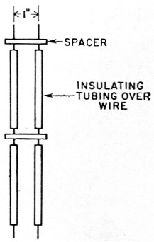
Fig. 3. This sketch shows details of DL1FK's open-wire line. Flexible antenna wire is fed through spacers and sections of insulating tubing. No fastening is necessary.
Adjustment
Since the transmission line is tuned, no adjustment of the driven element is necessary. The parasitic-element tuning may be done with the antenna elevated 10 feet or so above ground, if it is impracticable to do it at higher elevation. Approximate resonant frequencies for the parasitic elements are as follows:
| Operating f | Director | Reflector |
|---|---|---|
| 28,400 kc | 29,400 kc | 27,600 kc |
| 21,250 kc | 21,700 kc | 20,800 kc |
| 14,250 kc | 14,550 kc | 13,950 kc |
The parasitic element lengths should initially be slightly longer than the dimensions given in Fig. 1B. The reflector is adjusted first, and then the director. The capacitor should be adjusted for the 14 Mc band, then the over-all length adjusted for the 21 Mc band. After each adjustment at 21 Mc, the capacitor should be retuned for 14 Mc. After the 15/20-meter elements have been tuned, the 10-meter elements may be pruned. In doing this, I simply wound the ends of the wire up on an insulated screw driver. In this way, the length of the element can be easily increased again by unwinding if it is found that it has been made too short.
When the resonant frequencies begin to approximate those given above, the final adjustment should be made with a field-strength meter, checking for minimum backward radiation, since this indication is sharper than the forward radiation. Adjustment of the capacitor will be found to he quite critical. In making the f.s. measurements, care should be taken to keep the transmitter output coupling or tuning adjusted for constant input to the transmitter.
In coupling the line to the transmitter, I use a separate antenna coupler for each band, fed with low-impedance line from the transmitter. The couplers are adjusted for the lowest s.w.r. on the low-impedance line at the design frequency (see ARRL Antenna Book or ARRL Handbook).
With the transmitter at DL1FK running about 100 watt input, outstanding signal reports have been received from all points on the globe in spite of the fact that the antenna is not ideally situated in respect to surrounding objects, as can be seen in the photograph.
Notes
Richard Auerbach, DL1FK.