65 watt at low cost
Discarded TV set as a component source.
Those of you who know Lew McCoy personally realize that he is a man of many talents. High on the list is his ability as a sleight-of-hand artist - he can make cards and coins appear and disappear with the greatest of ease. He certainly displayed some of his skill as a magician when he took the broken down old TV set pictured at the left and after suitable manipulations came up with the very handsome little transmitter shown on the next page. In this article Mac shows you how you can perform this same magic and come up with a nifty transmitter of modem design and low cost.
Building a 65 watt multiband transmitter for about twenty dollars sounds a little ridiculous in these days of high prices. However, with a little judicious scrounging it is no problem at all. The transmitter described in this article was built for the most part from a junked TV set. TV sets from the 1948 to 1955 era have been "wearing out" and accumulating in TV repair shops. Investigation proved that these sets can usually be obtained for the asking or for a very slight charge. The TV shops are usually glad to get rid of them.
For our purposes the TV set doesn't have to be in working order as long as it has a usable power transformer (some models didn't use transformers). When acquiring the TV set, make sure the power transformer isn't burned out. All you have to do is smell the transformer - if it's bad you will be able to tell by the odor of burnt insulation. Also, if the set has the tubes in it, check to see if it has a 6K6 and a 6BG6; these are the tubes you'll need for the rig. Or you might ask the TV man if he has some "old" 6K6s and 6BG6s. You'll probably find he has a collection of them taken from old sets and will be glad to let you have a few cheap (this was true in our case). You might as well take advantage of a good thing and also try to promote a tuning capacitor from an old a.c.-d.c. table radio. C5 in Fig. 1, the tank capacitor of the final amplifier, is such a capacitor. Also, some of the old TV sets didn't have power-supply chokes, using the speaker field winding instead, and this won't serve our purposes. Therefore, try to get a set with a choke in it. Practically any TV set with a transformer power supply will do, but if you can, try for an RCA chassis. The transformers in these sets give slightly more voltage than some of the other types.
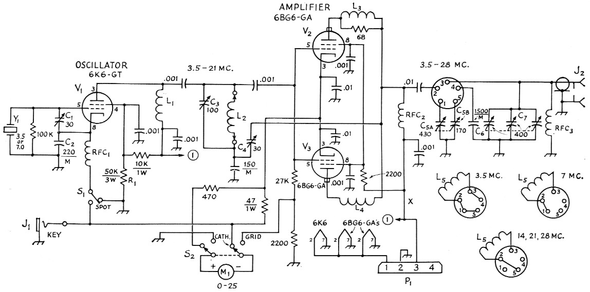
Fig. 1. Circuit diagram of the transmitter. Unless otherwise indicated, capacitances are in pF, resistances are in ohm, resistors are ½ watt. Fixed capacitors marked M are mica; others are disk ceramic.
| C1,C4 | 3-30 pF mica trimmer. |
| C2 | 220 pF mica. |
| C3 | 100 pF variable (Hammarlund HF-100). |
| C5 | Two-section receiving variable, approx. 170 pF and 430 pF (Allied Radio 61-H-065 or Philmore 9045). |
| C6 | 1500 pF mica. |
| C7 | Three-section receiving variable, approx. 400 pF per section (Allied Radio 60-H-726 or Philmore 9047). |
| J1 | Open-circuit phone jack. |
| J2 | Coax chassis receptacle, SO-239 or phono jack. |
| L1 | 25 uH r.f. choke (Millen 34300-25). |
| L3,L4 | 3 turns No. 14 wound on a 68 ohm 1 watt resistor. These are parasitic suppressors, and they are both connected as shown at L3. The 68 ohm resistor was omitted at 14 in the drawing to save space. |
| M1 | 0-25 milliammeter (Shurite Model 950 or 550). |
| P1 | Four-prong plug, cable mounting (Amphenol 86PM4). |
| R1 | 50 kΩ, 3 watt (three 150,000 ohm 1 watt resistors in parallel). |
| RFC1,RFC2,RFC3 | 1 mH r.f. choke (Millen 34300-1000). |
| S1 | S.p.d.t. toggle. |
| S2 | D.p.d.t. toggle. |
| Y1 | 3.5 or 7.0 Mc crystal, as required. |
Circuit details of the transmitter
The transmitter can be operated on any band from 3.5 Mc through 28 Mc at inputs up to 70 watt, depending on the plate voltage of the amplifier. A 6K6 crystal-controlled oscillator is used. The input side of the tube operates at the crystal frequency, while the output side can be tuned either to the crystal frequency or multiples of it. In other words, the 6K6 operates as a combination oscillator and frequency multiplier. L1L2, with C2, serves as the oscillator tank circuit.
Either 80 or 40 meter crystals can be used, depending on the band. For 80 meter work, a 3.5 Mc crystal is used. For 80, L1 is the tank coil and L2 is not required for this band. The same crystal will furnish adequate drive on 40, with the oscillator doubling, and on 20 with the oscillator quadrupling. Alternatively, a 40 meter crystal can be used for 7 Mc, or for 14 Mc with the oscillator doubling. A 40 meter crystal is used for 21 Mc with the oscillator tripling, and for 28 Mc with the oscillator doubling to 14 Mc and the amplifier doubling to 28 Mc.
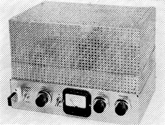
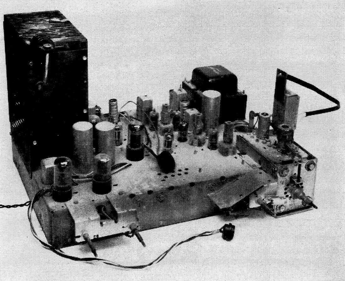
This is a view of the completed transmitter, the one that McCoy created by waving a magic wand (soldering iron, that is) over the broken-down old relic shown on the opposite page. (Oh, sure-he had to buy a few extra parts.) At the far left on the chassis front is the crystal and to its right are S1, C3, and S2 in that order. The amplifier tank and loading capacitor controls are to the right of the meter.
The amplifier tank circuit is a pi network designed to work into 50 or 70 ohm loads. The tank capacitor, C5, is a two-section superhet variable. One section has a maximum capaci tane of approximately 170 pF, and the other section 430 pF. Both of these sections are connected in parallel when the 80 meter coil is plugged into the coil socket. For 40 meter, only the 430 pF section is used, and on 20, 15 and 10, just the 170 pF section. A three-section t.r.f.-type variable capacitor, C7, with all three sections connected in parallel, is used for the pi loading control. In addition, a fixed 1500 pF mica, C6, is connected into the circuit when the 80 meter coil is plugged into the coil socket.
The amplifier is neutralized to prevent self-oscillation. A capacitive-divider neutralizing system consisting of C4 and the 150 pF mica capacitor is the neutralizing circuit. RFC3 serves as a safety precaution in the event that the plate blocking capacitor should break down, in which case the d.c. +B would be on the antenna system if the r.f. choke were not there to short-circuit it.
Cathode keying is used in the transmitter. Both stages can be keyed or just the amplifier. Better keying results if the oscillator is left running and the amplifier alone is keyed. This is taken care of by grounding the cathode of the oscillator with S1. (If amplifier keying is used, the oscillator must be turned off with S1 when receiving, otherwise the oscillator signal will be heard in the receiver.) S1 can also be used as a spotting switch to turn on the oscillator without turning on the amplifier.
A 0-25 milliammeter is used to measure either the grid current or cathode current of the amplifier. In the grid position, the full-scale reading is 25 mA. In the cathode position, a multiplier of 10 is used, giving full-scale deflection of 250 mA.
Here is a shot of the rig with the top screen removed. L2 is visible between the oscillator tube (at the right) and the amplifier tubes. The amplifier coil is at the left. Along the back of the chassis from the left are the output jack, power cable, and key jack.
Power supply
If you'll look at the photographs you'll see that there is no power supply shown for the rig. The answer is simply that you don't have to build a supply - the TV set already has one in it!
If you don't mind having the supply on the TV chassis, it is quite simple to make use of the already-constructed supply. All the tubes except the rectifier should be removed from the TV set and three leads are brought from the set to the transmitter. A ground lead is required, a lead from the 6.3-volt heater line, and the +B lead. The easiest method for getting the +B lead is to ask the TV serviceman to show you where the +B comes out of the power-supply filter. Otherwise you'll have to trace out the wiring to find the point where the +B leaves the last electrolytic filter capacitor.
If you want to strip the TV set down, you can get another chassis and build yourself a supply. Fig. 2 shows the circuit of a supply that will do the job. This is a capacitor-input supply of the same type used in the TV set. Upon examining the TV set, you'll find several electrolytic capacitors, usually in metal cans. The values will probably range from 8 µF to 40 µF or more at 450 volt, depending on the set. Any of these values can be used for Cs and C9, but if two different values are available, use the larger for C9. However, be sure you use capacitors with the 450 volt rating. You'll find some values with much lower working-voltage ratings; these capacitors are usually used in audio circuits where a high working voltage isn't required. Ls, the power-supply choke, may range in value from 2 to 10 henry, depending on the set. The bleeder resistor, R2, should be about 50,000 ohm at 10 watt. Incidentally, the metal can of the electrolytic capacitor is the negative side of the capacitor. Be sure you observe correct polarity when installing the capacitors in the supply. The B plus can be turned on and off with S4.
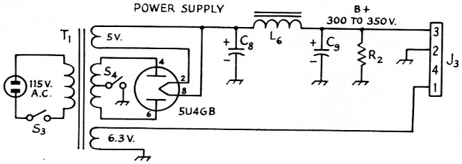
Fig. 2. Circuit diagram of typical power supply. See text for values.
| J3 | Four-prong socket. |
| S3,S4 | S.p.s.t. toggle. |
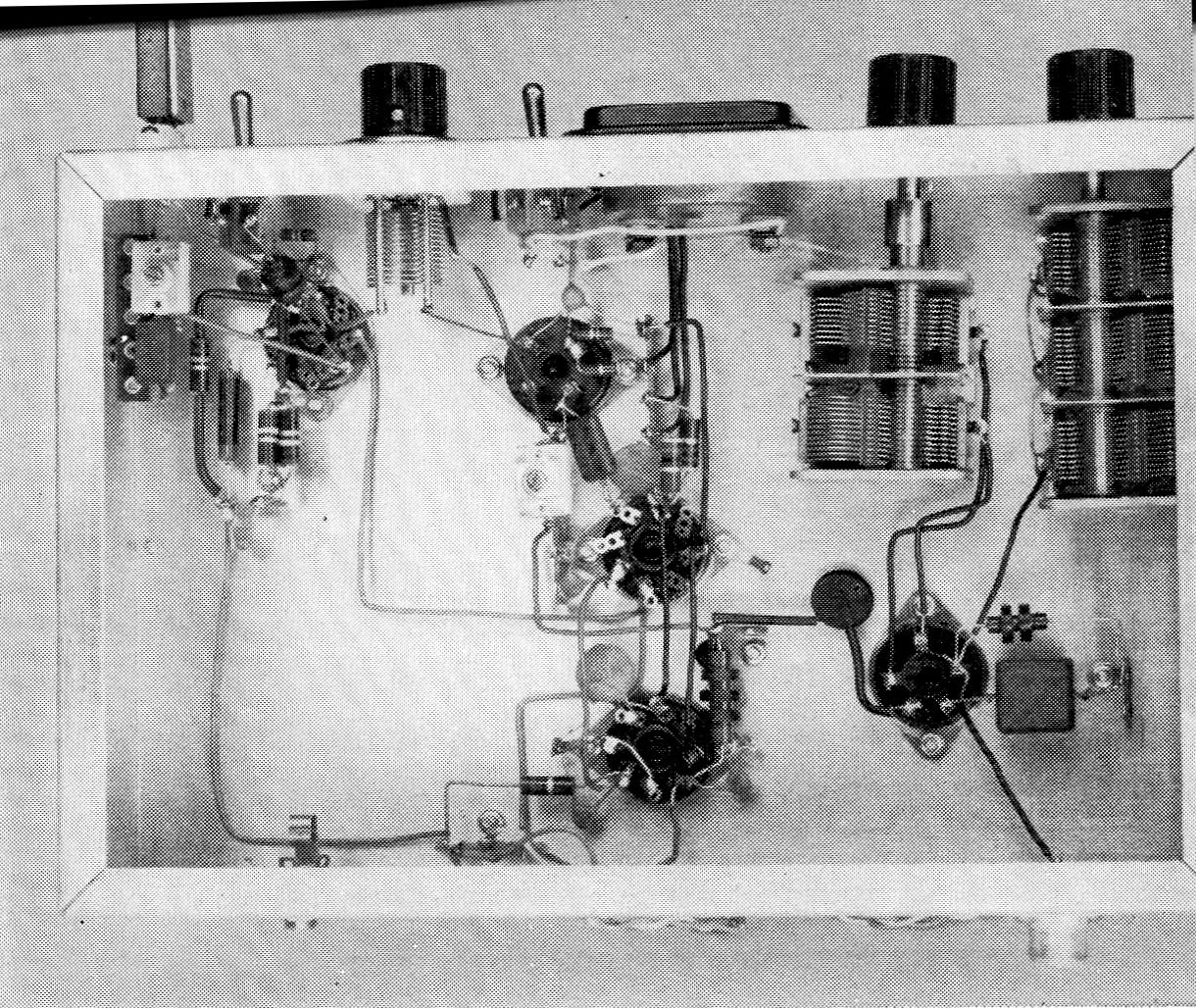
The oscillator components are grouped around the 6K6 socket visible at the upper left. Just below the toggle switch next to the meter is the coil socket for L. The two 66G6 sockets are at the center of the chassis. The two section variable capacitor at the upper right is C5 and C7 is to its right. Just below the two variables is the coil socket for L5. To the right of the socket are C6 and RFC3.
Construction details
A 3 × 8 × 12 inch aluminum chassis is used for the transmitter. Follow the general arrangement shown in the top and bottom views when mounting the components in place. C3 must be insulated from the chassis and fiber washers are used for this purpose. Be sure to allow sufficient room between C5 and C7. (The writer goofed on this score and had the two rotors striking each other when they were tuned near minimum capacitance!)
If you live in an area where TVI is a problem, you'll have to shield the rig. The top shield in the unit shown was made from a section of Reynolds' "do-it-yourself" perforated aluminum stock. Incidentally, we found this was the most expensive item in the transmitter, costing about three dollars!
The "fence" that runs around the top of the chassis is made from two sections of perforated stock, 2 inch wide and 21 inch long. The perforated stock comes in a 36 × 36 inch piece, so it is impossible to get a single length long enough to go around the entire chassis. The completed fence is 1¾ inch high with a ¼ inch lip which is secured to the chassis top with machine screws and nuts. The two sections are each formed into an L shape measuring 8 × 12 inch, the remaining inch being used at two of the corners for an overlap to fasten the two sections together with screws and nuts.
The sides of the shield are made from two pieces of perforated stock measuring 6½ × 20½ inches before folding. The side dimensions of the two pieces after folding are 7¾ and 11¾ inch; the extra inch is used for the overlap to connect the two pieces together. A one-inch flange is folded in around the top so that the overall height is 5½ inch. The top is made from a piece of stock 7¾ by 11¾ inches and is secured to the sides with machine screws and nuts. When the completed cover is slid down inside the fence and flush with chassis, the overlap is sufficient to prevent harmonic leakage, provided care has been used in folding the stock to insure a snug fit. No screws are needed to hold the cover down. This makes coil changing a simple chore because the cover can be removed and replaced quite easily.
The cable used to connect the transmitter to the power supply can be made any length, depending where you install the power supply.
Making the coils
Table 1 gives all the necessary information on the plug-in coils. The coils are made from commercially wound coil stock, so making the coils is a fairly simple job. The oscillator coils are mounted inside the plug-in coil forms and the amplifier coils are on the outsides of the forms. The Air Dux coil stock specified in Table 1 has exactly the right diameter to fit over the forms.
| L2 | 7 Mc - 29½ turns No. 20, 16 turns per inch, ¾ inch diam. 14-21 Mc - 7½ turns same (B & W Miniductor 3011 or Illumitronic Air Dux 616T). |
| L5 | 3.5 Mc - 13 turns No. 14, 6 turns per inch, 1¾ inch diam. 7 Mc - 8 turns same. 14 Mc - 5 turns same. 21 Mc - 3½ turns same. 28 Mc - 2½ turns same. (Illumitronic Air Dux 1406T). |
| Note: A single length of Illumitronic 616T or B & W 3011 will suffice for the 7 and 14, 21 Mc oscillator coils. One length of Air Dux 1406T is sufficient for all the amplifier coils. The L2 coils are mounted in four-prong plug-in coil forms, 2 required (Amphenol 24-4P or Allied Radio 71-H-713), and the L5 coils in five-prong forms, 5 required (Amphenol 24-5H or Allied Radio 71-H-714). | |
When cutting the oscillator coils from the original stock, allow three extra turns on the 20, 15 meter coil and five extra turns for the 40-meter unit. When these extra turns are unwound from the coil stock you'll have sufficient lead length to reach through the prongs on the plug-in coil forms. Before soldering the prongs, take a file and file off the nickel plating from the ends of the prongs, so that the solder will take more readily. Also, hold the prong being soldered with a pair of pliers to prevent too much heat from reaching the base of the coil form and loosening the prong. Be sure to clean off any resin that may stick to the prongs after soldering. Use four-prong coils for the oscillator coils and five prongs for the amplifier.
When making the amplifier coils, jumper the prongs as shown in Fig. 1.
Tuning up the rig
The first step in testing is to neutralize the final amplifier. The lead that feeds the plates and screens of the 6BG6s should be disconnected at point X in Fig. 1 so that the only voltage on these tubes is the heater voltage. Plug in a 40 meter crystal and the 40-meter grid and plate coils. Turn on the power and let the oscillator tube warm up. Switch SI to read grid current. Next, close the key and adjust C3 for a grid-current reading of 4 to 5 mA. Set C7 at maximum capacitance (plates fully meshed) and then tune C5 through its range. At one point you should notice a dip in the meter reading. Next, carefully adjust the neutralizing capacitor C4 so that the least amount of change occurs in the meter reading when C5 is tuned. When you find this point, the amplifier should be neutralized. In the rig shown here, this point was near the maximum-capacitance setting of C4. The plate and screen leads may now be reconnected - remembering to turn off the power first.
A dummy load should be used for testing the amplifier, and a good one for this purpose is a 60-watt lamp bulb. Connect a lead from J2 to the center contact on the base of the bulb and another lead from chassis ground to the threaded portion of the lamp base.
Plug in an 80 meter crystal and the 80 meter coil, turn on the power, and let the transmitter warm up. Set both C5 and C7 at maximum capacitance, plates fully meshed. Switch S2 to read grid current and close the key. Tune C3 for a grid-current reading of 2 to 4 mA. Don't hold the key down any longer than it takes to tune up for grid current, as the final will be out of resonance and will draw excessive plate current. This could cause permanent damage to the tubes. Next, switch S2 to read cathode current and close the key again. Tune C5 for a dip in the meter reading; this will indicate that the final is tuned to resonance. Start decreasing the capacitance of C7 while keeping the amplifier in resonance (at the dip in the meter reading) by adjusting C5. The light bulb should start to light up and get brighter as you adjust C5 and C7. The 6BG6s are good for 100 mA per tube, so you can load the amplifier to about 200 mA. Our TV set gave a plate voltage of 320 under a load of 200 mA, which amounts to 64 watt input.
The same tune-up procedure should be followed for the other bands. When tuning up on 20 and 15 there are two settings of C3 which will give you grid drive to the final, depending on which band you want. The setting nearest maximum capacitance is 20 meters and the one near minimum is 15. One way to check the correct tuning points is with an absorption wavemeter. In fact, an absorption-type wavemeter is almost a "must" in any ham shack, particularly a Novice's. The wavemeter will show you what band your transmitter is tuned to. Details for simple wavemeters can be found in the Measurements chapter of The Radio Amateur's Handbook.
The feedback capacitor, C1, in the oscillator circuit should be adjusted with the rig tuned up for 15 meter. Adjust C1 for a grid-meter reading of no more than 4 mA on this band. This adjustment need not be changed for other bands with crystals of ordinary activity.
With the TV set we used, the plate voltage on the 6K6 was 320 volt, the screen, 250. Screen voltage of the 6BG6s was 300 volt. In order to get the 100 mA plate current per 6BG6 the screen voltage should be approximately 300 volt.
After you've checked the rig out with a dummy load you are ready to put the transmitter on the air. If you don't already have an antenna and antenna coupler, the Handbook will give you information on different types of both.
Any antenna system, or antenna-plus-coupler combination, that can be adjusted to offer a load of about 50-75 ohm can be used with this transmitter.
Lewis G. McCoy, W1ICP.