A pulsed, crystal controlled signal generator
With this generator and an oscilloscope you can adjust your receiver and actually watch what happens to its gain and signal-to-noise ratio. Though described for 436 Mc., the method can be used at any other frequency.
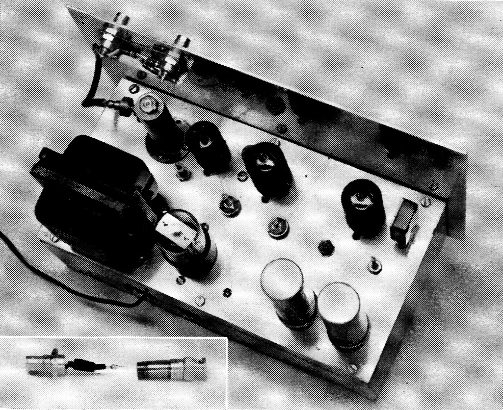
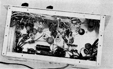
Top rear view of the signal generator. Output jacks J1 and J2 and the built-in attenuator are mounted on the panel in the upper left corner. From them, a short length of coax runs to the coaxial tank, Ls. On a line with it from left to right are the 6AK5, the 12AT7s, and the crystal. The test point is just visible to the left of the middle tube. On a line behind the tubes are the tuning screws for C2, L4, L3, L2 and L1. Toward the rear of the chassis are the power transformer, the 6X5 rectifier tube and filter capacitors C4 and C5. The inset shows the external attenuator with P1 on the right and P2 on the left.
In connection with a radio-telescope project on which the writer has been working for several months, it became necessary to devise a simple means of checking antennas and receivers at 436 Mc. After struggling for some time with an expensive commercial signal generator which drifted in frequency, it was decided to build a crystal-controlled generator. Further thought established that if the generator were pulsed, an oscilloscope could be used to view the output of the receiver, and the scope display would look very much like a type "A" radar presentation. This display (see Fig. 1) shows the effect of any adjustment which changes the signal amplitude or affects the signal-to-noise ratio.
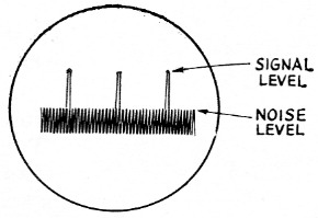
Fig. 1. Receiver output as seen on an oscilloscope. Height of signal pulses above the noise "grass" indicates the signal-to-noise ratio.
The generator described here was sketched out and built in less than a day, and it was intended to use as few parts and be as inexpensive as possible. Although this unit was designed for output at 436 Mc., the pulsing method could be used with an r.f. system for any other band. A perfectly satisfactory crystal turned out to be one of the radio control crystals for use at 27.25 Mc. and selling for less than $3.00. As shown in Fig. 2, four doublers bring the frequency up to 436 Mc., with sufficient power to make antenna pattern measurements. One 12AT7 serves as oscillator and first doubler. The capacitor across L1, the oscillator plate coil, is required to raise the tank Q enough for third overtone operation of the crystal on its marked frequency. Another 12AT7 provides two more frequency doublers. These are followed by a 6AK5 doubler with a coaxial output tank. The latter gave better efficiency than any of the coil-capacitor arrangements tried and is simple to make.
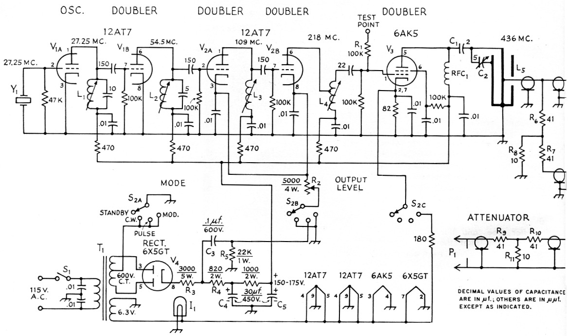
Fig. 2. Circuit diagram of the signal generator. Unless indicated otherwise, resistors are ½ watt. 10 nF capacitors are disk ceramic; others are tubular ceramic, except as specified below.
| C1 | 2 pF tubular ceramic. |
| C2 | 1-5 pF plastic trimmer (similar to Erie 532-A). |
| C3 | l00 nF paper, 600 volt. |
| C4,C5 | 30 µF electrolytic, 450 volt. |
| I1 | 6.3 volt pilot bulb. |
| J1,J2 | Coaxial chassis receptacle (Amphenol 31-102). |
| L1 | 15 turns No. 28 enamel close-wound on ¼ inch iron slug-tuned form (National XR-83). (North Hills 1300-C or Miller 20A106RB1 coils also usable.) |
| L2 | 6 turns No. 22 enamel close-wound on 3/8 inch iron slug-tuned form (National XR-93). (North Hills 1300-B or Miller 20A107RB1 coils also usable.) |
| L3 | 6 turns No. 16 tinned, ½ inch long, on 3/8 inch brass slug-tuned form (National XR-92). |
| L4 | 2 turns No. 16 tinned, ½ inch long, on 3/8 inch brass slug-tuned form (National XR-92), center tapped. |
| L5 | Coaxial tank, see text. |
| P1 | Coaxial plug (Amphenol 31-212). |
| P2 | Coaxial receptacle (Amphenol 31-206). |
| R1 | 100 kΩ. |
| R2 | 5000 ohm 4-watt wire-wound potentiometer. |
| R3 | 3000 ohm 5 watts. |
| R4 | 820 ohm, 2 watts. |
| R5 | 20 kΩ, 1 watt. |
| R6,R7,R9,R10 | 41 ohm. |
| R8,R11 | 10 ohms. |
| RFC1 | 25 turns No. 26 enamel spaced wire diameter on ¼ inch-diameter form. |
| S1 | S.p.s.t. toggle switch. |
| S2 | 1-section, 3-pole, 4-position rotary switch (Centralab PA-5 switch section and PA-300 index). |
| T1 | Power transformer, approximately 600 volt c.t. at 50 mA, 6.3 volt at 1.375 A (Triad R-5A suitable). |
| Y1 | 27.25 Mc radio control crystal. |
The power transformer used has somewhat higher voltage than actually needed. This surplus is put to good use, however, when pulsed output is used. Figure 3A shows the waveform at the junction of R3 and R4, this being simply a train of 120-cycle pulses from the rectifier. The differentiating circuit composed of R5 and C3 modifies this waveform to that shown in Fig. 3B. This voltage is applied to the cathodes of both sections of V2 when the mode switch S2 is in the "pulse" position. These two doubler stages are normally near cut-off, but the sharp, negative-going pulses drive them into conduction for a few milliseconds once every 1/120th second.
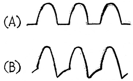
Fig. 3. Waveforms present (A) at the junction of R3 and R4, and
(B) after passing through differentiator C3-R5.
While the unit was primarily intended as a pulse generator, S2 does provide for other modes of operation. In the "c.w." position, it grounds the cathodes of doublers V2A and V2B, these stages operate normally, and continuous output is obtained. These cathodes are also grounded when S2 is switched to "mod.," but here sine-wave modulation is accomplished by applying about 2 volts a.c. to the cathode of the 6AK5 final stage. The 60 cycle modulation envelope may not be a perfect sine wave for all possible adjustments of the tuned circuit, but it is perfectly satisfactory for test purposes. For all three output conditions, R2 controls the output signal level by varying the bias on V2A and V2B. In "standby" position, 82 removes high voltage from the whole r.f. section by ungrounding the high-voltage center tap of T1.
A built-in 50-ohm-to-50-ohm pad between J3 and J2 reduces the output at the latter terminal by 20 dB and also isolates a load connected there from the generator. A separate 20 dB attenuator can be plugged into J2 to cut the output still further, or into J1 to provide two identical but isolated outputs.
Bottom view. From left to right along the top (front) are mode switch S2, excitation control R2, the pilot light, and power switch S1. The open end of the coaxial tank can be seen between the pilot light and S1. The tube sockets are on a line to the left of the tank, and slug-tuned coils L1, L2, L3 and L4 and the tubular trimmer C2 form another line immediately below them. Power-supply components are arranged along the rear apron.
Construction and adjustment
The generator is built on a 5 × 9½ × 3-inch aluminum chassis. In the original version, the chassis top was sawed out, and the components were assembled on a 5 × 9½ inch plate which then replaced the original top. Wiring up the parts was easier on an open plate than down in the depths of a chassis. As an alternative arrangement, one might build the generator on a plate, get it working, and then fasten the plate to the open side of an inverted chassis of the same size. The panel is simply a 7 × 10½ inch piece of aluminum.
R.f. components are lined up along the front of the unit as shown in the photos while the power supply is located to the rear. S2, R2, the pilot lamp and S1 are mounted on the front apron. Aside from keeping all leads as short as possible in the r.f. section, about the only construction feature requiring special note is the coaxial tank circuit. The outer conductor is a 2½ inch length of 1 inch diameter brass pipe with a snug-fitting brass washer soldered into the top end. A larger washer soldered to the outside of the pipe at the opposite end serves to fasten the tank to the chassis. The inner conductor is a 2½ inch length of ¼ inch brass rod threaded at one end for a distance of about 3/8 inch. The threaded end of the rod goes through the washer at the top of the tank and is secured by two nuts. The rod can be drilled and tapped at the opposite end to take a 6-32 screw, and a lug placed under this screw will serve for connection to C1 and C2.
R.f. output is taken from a tap on the inner conductor of the coax tank about 34 inch from the shorted end. Several methods of making the tap are satisfactory. A simple one is to solder an insulated wire to the M-inch brass rod and bring it out through a hole in the 1-inch brass pipe.
Another way is to drill and tap the rod for a 6-32 screw which can project out through a clearance hole in the pipe. The special fitting shown in the photographs was made up so that the output tap could be shifted. This is unnecessary since a fixed tap point has proved perfectly satisfactory.
From the tap, a short length of coax goes to J1 on the panel. Resistors R6, R7 and R8, which make up the built-in attenuator, run along a strip of flashing copper or brass shim stock bent into an L shape. This is held to the panel by the nuts used to mount Ji and J2. The coax shield braid and the grounded end of Rs are soldered to this strip. The external attenuator, shown partially disassembled, is made with fittings P1 and P2 and a 1_1/8 inch length of 7/16 inch diameter brass pipe. This pipe is threaded at both ends with 32 threads per inch so that it will screw into the two fittings. R9 is soldered to the removable center contact of P1. R10 runs from the other end of R9 to the center contact of P2. One end of Rn goes to the junction of R9 and R10, and the other end is soldered through a hole in the outer portion of P2. A couple of turns of tape around the resistors will insure against shorts when the assembly is screwed together.
Tuning, up to and including the 218 Mc circuit, can be checked with a grid-dip meter used as an absorption wavemeter. If you are as lucky as we were, everything will tune up using only a v.t.v.m. plugged into the test jack to indicate alignment of the first four tuned circuits. With the function switch in the c.w. position and the output level control near maximum, the negative voltage at this point should be about 2.5 to 3 volt. Even if you have to do a little coil pruning or squeezing, this is quite simple with a grid-dip meter. The S meter on a 436 Mc, receiver can then he used to indicate maximum output of the 6AK5 stage when tuning the coaxial tank.
Each of the 12AU7 stages draws about 3 mA plate current with 175 volt applied to the 470 ohm decoupling resistors. Combined plate and screen current for the 6AK5 will be about 4 mA. There is probably no real need to measure these currents, however, if the specified voltage is obtained at the test point and there is output at 436 Mc.
Application
The generator has proven to be quite useful in comparing the gains and signal-to-noise ratios of various r.f. preamplifiers. Two methods of making comparative receiver checks have been used. One involves the use of 40 dB of attenuation (both the built-in and external pads in series) between signal generator and receiver to tie down the source impedance seen by the load. The second method makes use of a test antenna erected some distance from and in front of the regular receiving antenna. The signal generator feeds the test antenna through Ji without the attenuator in the line. Different receivers can then be compared by connecting them to the regular receiving antenna. It might be emphasized that the pulse technique aids greatly in getting parametric amplifiers going for the first time. The generator output can be run fairly high, and some signal will feed through the paramp even when it is not working properly. The effect of each adjustment can be seen clearly.
The most satisfactory way of tying the oscilloscope to the receiver is to connect it directly across the detector load resistor. The average audio stages are not good enough to pass narrow pulses; hence the need to connect ahead of them. In one receiver, the high end of the detector load resistor was connected through a 47,000-ohm resistor to a coaxial connector on the rear apron. Shielded wire must be used to prevent feedback at the i.f. and preserve the receiver's stability.
Other instruments have been used for actual quantitative measurements, although it should be possible to calibrate the output control, R2. Another possibility would be the inclusion of an r.f. v.t.v.m. calibrated in microvolts or millivolts at the output circuit. A further refinement would be voltage stabilization of the crystal oscillator plate voltage. A VR105 and suitable dropping resistor should prove satisfactory.
Robert L. McFarland.