Home-brew custom designing
How to make professional-looking enclosures.
For years, most home-built enclosures have been confined to the square-edge knuckle-gouging outline with the protruding bolt heads of the Erector-set era. Now K6SNO comes along to show us how simply the use of rivets and a few easily-made rounded corners can transform the appearance to rival the professional.
With the growing popularity of commercial equipment in the past decade, the appearance of many ham shacks has improved considerably. However, there are still some hardy individuals who remain "do-it-yourselfers" and build their own equipment. Quite often the difference in appearance between the home-brewed equipment and the commercial gear is quite striking. If the builder has a little bit of mechanical ability and the ordinary garden variety of hand tools in his shop, his equipment can be made to look just as good as the commercial variety, yet be distinctive and fit the nooks and crannies available.
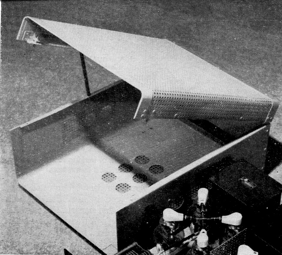
One would hardly guess that this clean-looking enclosure was not a manufactured item. Similar enclosures of any desired size and shape may be simply made in the home workshop by following the procedure described in the text. (The amplifier in the foreground will be described in a subsequent issue.)
Shape factor
The size and configuration of commercial ham gear does not always fit the shack or desk to best advantage, to say nothing of the automobile. The electronics industry (and hams) long ago standardized on the 19-inch panel width. Consequently most of the gear produced commercially or at home takes up 20 to 22 inch of desktop width. A few manufacturers recently have been making equipment in smaller panel sizes. The average amateur has limited space in which to pursue his hobby. If he is fortunate, he may have an operating desk 60 inch wide by 30 inch deep. More often it may be a 42 or 54 inch desk.
The usual array of equipment consists of a receiver, exciter, and final amplifier. If these are each 20 inches wide, they will just fit on a 60 inch desk, provided that ventilation requirements are ignored. In addition, there are usually accessory pieces of gear that are desirable to have at the operating position, such as a scope, frequency meter, s.w.r. bridge, control box, and beam-position indicator. This requires stacking the gear up, impeding ventilation, and making servicing and operating cumbersome. If the width of this equipment were compressed slightly, even at the expense of increased depth, much better use of the desk-top space would result.
A couple of years ago, the author built the "Single-Sideband Package" described by W6TEU.(1) However, instead of building it to the 19-inch width, the front panel was made 14 inches wide by 8 inches high and the chassis extended to a depth of 17 inches. Having acquired one of the new commercial receivers with a 14 inch panel width, the saving in desk-top space was quite revealing. The linear amplifier at K6SNO was a home-built affair consisting of four 811As with grounded grids. The amplifier and power supply was housed in a standard cabinet 21 inches wide by 13 inches high and 15 inches deep. It was considered quite a feat to get a kilowatt p.e.p. in a package of that size. However, contentment with that size was short-lived as there were other pieces of gear needed on the desk. So, it was decided to see if it could be packaged in a cabinet to match the exciter. This being the second attempt at building a cabinet of this configuration (14 inch wide by 8 inch high by 17 inch deep), the job was much easier and the results quite rewarding. It takes only a week end of time and is quite easy on the pocketbook.
Since it is not intended that this size of cabinet be used as a standard, this article will attempt only to describe some of the techniques used. The builder is encouraged to establish the con-. figuration best suited to his personal needs. The use of sheet-metal shop facilities is not needed and, since the author has had no previous sheet-metal working experience, it can be assumed that anybody can duplicate the results shown in the photograph.
Materials
While searching for sheet-aluminum stock, we ran across an unexpected source of supply. Job printing shops use sheet aluminum coated with selenium oxide for a photocopying process. After the coating is depleted, the plates are thrown away. By cautious removal of the selenium oxide (it is highly toxic) some excellent sheet stock is available. Of course, there are many other sources of suitable sheet-aluminum stock. To provide a cover that would afford adequate ventilation while providing r.f. shielding, a sheet of "do-it-yourself" perforated aluminum should be obtained. To make the cabinet for the amplifier mentioned, three sheets of the plate stock described, each measuring 15½ by 20½ inches, slightly less than 1/8 inch thick, were obtained. From the hardware store we got one 30 × 30 inch sheet of perforated aluminum (which is three times the requirements), 100 aluminum rivets, 12 inch of piano hinge, and a can of spray enamel. The total tab, including tax, was $5.73.
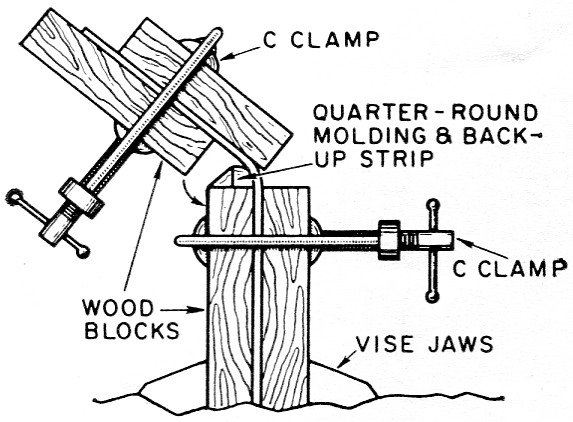
Fig. 1. Sketch showing method of making rounded corners. Procedure is described in the text.
Smooth edging
The inside dimensions of this cabinet were to be 14 inches wide by 8 inches high by 17½ inches deep. This accommodates a standard chassis of 13 by 17 by 3 inch. The side pieces were made first. A piece 18½ by 8_3/8 inch was cut out. One inch of the end of this piece, to be used as the front, was folded back flat on itself to provide a finished edge of double thickness. See Fig. 2A. By putting this fold in the vise and pressing it out flat, a very neat fold can be produced to give the front edge of the cabinet a finished appearance. The vise jaws should be covered with aluminum to prevent marking the cabinet material.
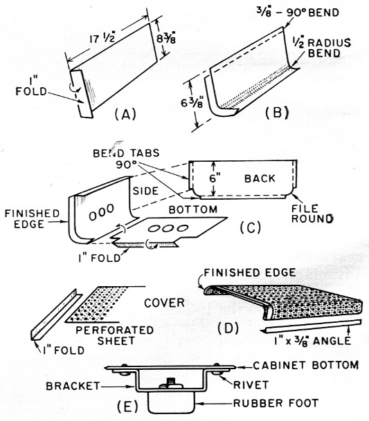
Fig. 2. Bending details.
A Forming front edge of side piece.
B Rounding bottom of side piece.
C Joining of side, back and bottom pieces.
D Forming front edge for perforated cover from angle stock, and bending side ends of cover.
E Bracket for rubber-foot mounting.
Ventilation
To provide ventilation at the sides and bottom of the cabinet, several holes were punched with a standard socket punch. A strip of the perforated stock was riveted on the inside of the cabinet to cover those holes so good r.f. shielding was maintained while letting the air circulate. This cabinet design provides excellent r.f. shielding for TVI protection, but it should be remembered that aluminum does not shield magnetic 60 cycle a.c. fields very effectively.
Making rounded corners
The sheet-metal bending jig or brake for making the rounded corners is made up of scraps of one inch board of appropriate length. On one of these, fasten a strip of ½ inch quarter-round molding with finishing nails, and countersink the heads. Back this up with a piece of scrap wood planed down as illustrated in Fig. 1. The sheet metal is clamped, as shown in the sketch, to provide the ½ inch radius bends for the bottom edge of the cabinet and for the top edges of the cover. The square-edge bends are made in the conventional manner by clamping at the square edges of the boards. Fig. 2B shows the side piece with the rounded bend. A 90 egree bend is made 3/8 inch from the top of this piece to provide the lip against which the cover closes. Of course, both left- and right-hand pieces must be made. The bottom is sized to the cabinet width, allowing 1½ inch on each side for overlap on the side pieces. The front edge of the bottom is folded back one inch in the same manner as the sides, making this fold down and under so that it will align with the finished edge of the side piece. After aligning the bottom with the side pieces and clamping in place, drill holes about 4 inch apart for the rivets. Insert the rivets from the bottom and burr them smooth so the chassis may be slid in and out without catching on them.
A word on use of aluminum rivets is in order. Drill the holes in the sheet metal so the rivets fit tightly. If 1/8 inch rivets are used, drill 1/8 inch holes. After inserting the rivet, cut off the protrusion with diagonal cutters so that only about 1/8 inch remains to be burred. A large nail set makes an excellent riveting tool and leaves a neat, smooth burr. To prevent disfiguration of the rivet head, place a piece of scrap aluminum stock between the rivet head and the anvil before wielding the hammer.
Making the cover
Measure out the perforated aluminum stock and cut to the appropriate dimension for the cover. Before bending the rounded corners of the cover, attach a finishing strip to the front. See Fig. 2D. Cut a 2-inch strip of the solid sheet stock to the same width as the perforated stock. Fold this exactly in the center so that there will be one inch on each side of the perforated sheet. By pressing this fold over the edge of the perforated sheet in the vise a good tight bond will be obtained. Again, to prevent marking of the aluminum by the vise jaws, line the jaws with some scraps of aluminum. The back of the cover is made of solid sheet stock similar to the cabinet back. Side frames for the cover are made of 1_3/8 inch strips, bent to provide a 3/8 inch lip to match the lip on the cabinet sides.
After the cover is bent to shape, the back piece and side frames are riveted in place. Banana plugs are fastened to the lips of the cover side frames near the front of the cabinet and they push through holes drilled in the lips of the cabinet sides to provide the cover latch and an electrical ground for the cover. See Fig. 3. The piano hinge is bolted to the back of the cover and cabinet, making sure that the electrical contact is good.
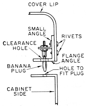
Fig. 3. Banana plugs used as cover catches.
To get good natural circulation of air through the cabinet, it should be mounted on feet to provide about one inch of space between the cabinet and desk. We found some stock rubber feet at the radio-supply house. They were only 3/8 inch thick, so brackets for mounting them were made up as illustrated in Fig. 2E. By riveting the brackets to the bottom of the cabinet and smoothing out the burrs, the chassis may be slid in and out without obstruction.
Finish
After the cabinet was completely assembled, it was given three coats of enamel. Aerosol spray enamel will give a professional-looking finish, if directions for use are followed. Several variations in finish may be obtained. In one case we sprayed the whole cabinet with a dark gray color and made the panel a battleship gray, which produced a pleasing contrast. In another case, the cover was left with the natural aluminum finish and the rest of the cabinet was sprayed with flat black. You can see counterparts of both schemes in commercial equipment.
This article will not go into all of the details of making this particular cabinet since each individual will no doubt have ideas of his own. However, it may give you some idea of the techniques used and you can let your ingenuity take over from here.
Tools
The perforated stock is quite light and easily cut with tin snips. The h-inch stock used for this cabinet cannot be cut with snips without bending and distorting the sheet stock. We used an old carpenter's saw that the junior op received in a Christmas tool chest some years ago. This saw has probably cut a thousand linear feet of aluminum with never a worry about sharpening it. The sheet stock should be clamped to the bench top to give it the required support for sawing. The edges will have heavy burrs but they are easily removed and smoothed with a file.
The basic tools used in these projects consisted of the carpenter's saw mentioned, a hammer, a square, six 3 inch C clamps, tin snips, an electric hand drill, file, chassis punch, diagonal cutters, pliers, and screwdriver. These tools, some sheet stock and a little "paper planning" should provide everything necessary for producing a custom-built cabinet that not only rivals commercial gear in appearance but offers the following advantages:
- The cabinet may be designed to fit your individual space requirements, including mobile.
- The cost may be kept very reasonable.
- You have the pride and distinction that goes with completely home-built equipment.
- It can be made "functional" - as heavy or as light as the gear requires - with good r.f. shielding if required, and built to contain as little or as much equipment as you choose.
- The equipment may actually have some resale value.
Notes
Floyd K. Peck, K6SNO.