A 75 meter s.s.b. transceiver
Compact filter rig for fixed, portable and mobile.
S.s.b. transceivers not only make for convenient operation (one knob tunes the receiver and sets the transmitter frequency) but also cut down the parts list by having many stages do double duty. This neat 5½ × 12 × 10 inch version uses an inexpensive surplus-crystal filter and simple circuitry throughout.
This project started out to be a mobile singlesideband transceiver, but a last-minute car trade (compact car with not-so-compact air conditioner) has necessitated a new designation. The rig will henceforth be referred to as a portable 75 meter s.s.b. transceiver, lower sideband.
Let me say that an undertaking of this sort is not an overnight project and also not the sort of thing a beginner should plunge headlong into. In other words, this is written for those who have had some experience in building receivers and exciters.
This is the pilot model and changes are constantly being made and tried. However, armed with the ideas and suggestions presented here, a workable transceiver can be produced. Those who are a little more astute in the ways of the electron may find improvements waiting to be made in some of the circuitry.
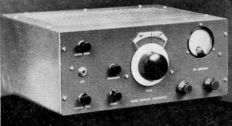
The 75 meter s.s.b. transceiver behind this pleasingly-simple panel measures only 13 by 10 by 5½ inch, but its construction does not require a watchmaker's skill. The s.s.b. signal is generated by means of a filter using surplus FT-241A crystals.
The design is about as straightforward as possible with no fancy frills. In describing the circuit, a sequence will be followed; we will go from input to output, first in the transmitter and then in the receiver section.
Carrier generator and balanced modulator
V1 serves two purposes - first, it is the r.f. source for the sideband generator; and second, it is the b.f.o. for the receiver. One half of the 12AU7 is a crystal oscillator, and the reason for using this particular oscillator configuration is simple - it just plain works well for me. The oscillator output is fed into V1B, which gives push-pull r.f. output for the balanced modulator. Trimmer C2 is used to balance the amounts of r.f. appearing on the plate and cathode of V1B.
The push-pull r.f. is then fed into the balanced modulator which can be either a 1N35 or a pair of 1N34s. It is not imperative that a 1N35 or a closely-matched pair of 1N34s be used, because a random pair of 1N34s works almost as well. Speech amplifier V2, a 12AX7, provides more than ample audio for the balanced modulator. The modulation or matching transformer, T1, is one of the surplus units popular in phasing-type exciters.
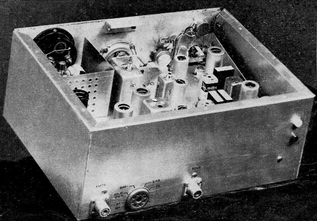
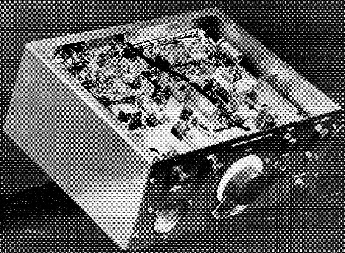
The components on the chassis in this inside view can be identified by comparing the picture with Fig. 4. The final amplifier is in one corner, boxed in by an L-shaped shield. Power-supply connections are made through the octal socket on the rear cabinet wall. Antenna send-receive switching is done externally.
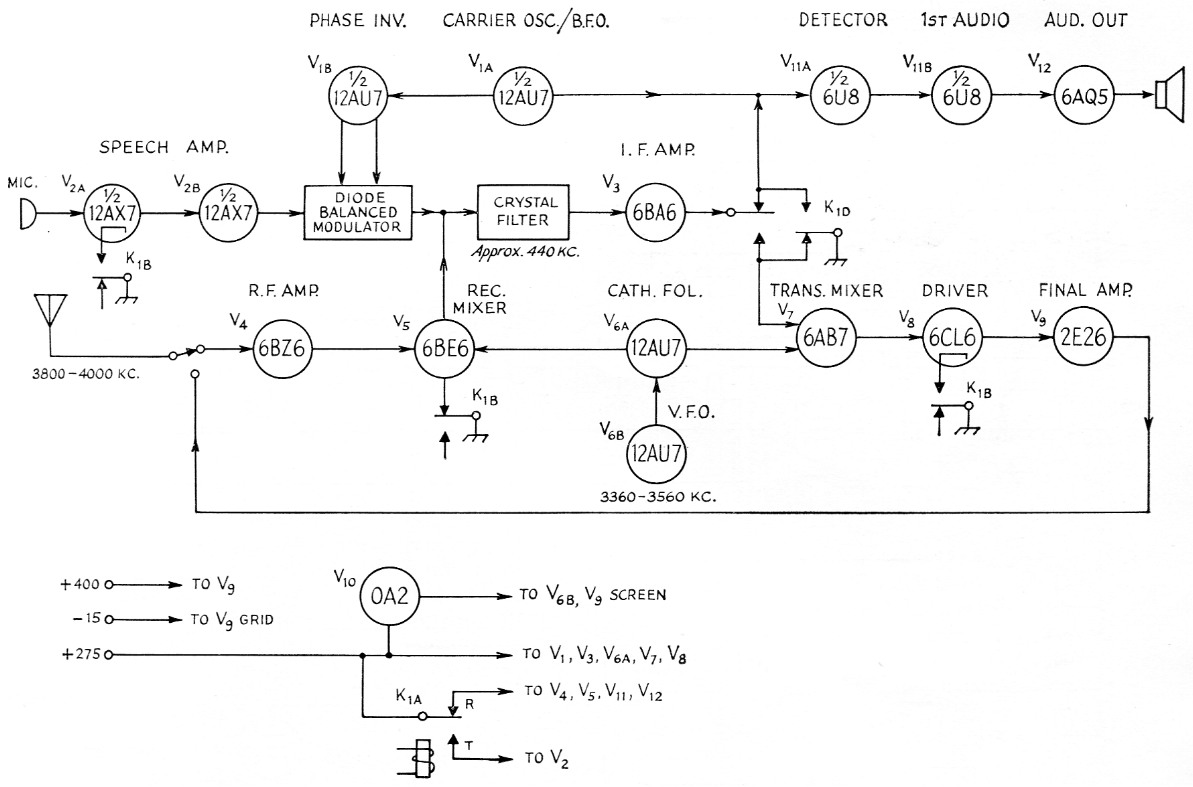
Fig. 1. Block diagram of the 75-meter s.s.b. transceiver. The switch and relay contacts are in "receive" position. Everything shown here, except the antenna switch, mike and speaker, is built into the unit described.
R1 is a panel-mounted balance control. This is adjusted for minimum carrier, and a good quality potentiometer (Ohmite AB or equivalent) should be used to assure smooth operation.
At the junction of R2 and C3 will be a doublesideband signal at the frequency of Y1. Effective shielding around the oscillator is important for good carrier suppression.
The sideband filter
Here is the heart of the rig, yet it is perhaps the simplest part of the whole transceiver. The filter consists of two replacement-type i.f. transformers and four cheap and easily-obtainable surplus low-frequency crystals. Technically speaking, the filter is a single half-lattice with two shunt crystals. Notice that this filter is turned around backwards from the way you usually see them; this is to achieve better matching to the low-impedance balanced modulator and the high-impedance receiver mixer.
The selection of crystals Y1-Y5 is strictly a matter of preference and availability, but if they are too far from 455 kc., the transformers will have to be padded. The crystals that were chosen for the original rig are:
Y1,Y2,Y4,Y5 Channel 38 (440.74 kc.)
Y3 Channel 37 (438.89 kc.)
Any co-channel selection around this frequency will work very well. Just make sure that each crystal is a good one, although they not need be exactly matched.
The i.f. transformers are not critical as to type, but I found that the ¾ inch-square Miller replacements specified gave a little less filter loss than others that were tried. This is important because you do need a little signal getting through (and that is through, not across) the filter.
After a little screw-twisting on the i.f. transformers, there should be a single-sideband signal at T3. Then comes V3, a stage of i.f. amplification. This is a lightly-loaded stage, so all wiring precautions should be taken to make the 6AB6 as stable as possible. Once again, i.f. transformer T4 is not critical, but a good quality unit should be used.
The V.F.O.
V6 is another 12AU7, half of which is the variable-frequency oscillator and the other half a cathode follower. This combination provides oscillator injection for both the transmitter mixer and receiver mixer. Mixing can be either additive or subtractive, and in this case the additive alternative was chosen. For example, assume the generator frequency is 440 kc, and a frequency of 3800 kc is desired; the injection frequency should then be 3360 kc.
Since this rig is for 75 phone, only 200 kc of bandspread is needed or desired. The general idea is to start with a good, sturdy, double-bearing capacitor of about 100 pF for C6, a total of about 600 pF for C5 (which is several smaller capacitors in parallel), and L3 wound as specified. Then sit down with a grid-dip meter and a receiver and go to work juggling. capacitance and pruning turns until the desired coverage is obtained. The tap on L3 should be about one third of the way from the cold end.
The dial assembly is a surplus item found in just about every junk box - the velvet vernier from a BC-375 or 191 tuning unit. Of course, a new National AM dial will work as well. The reference line is scribed on a piece of plastic which is spaced out from the panel enough to clear the rim of the dial.
Transmitter mixer and r.f. stages
The transmitter mixer stage, V7, uses a 6BA7. The only precaution here is to ground the signal grid in "receive" position with Kin. Otherwise there is enough feed through in Kic to excite the tube, thereby setting up complications.
The driver stage is a 6CL6 operating Class A. These tubes have a tendency to "take off," but the shielded L4 coil assembly, lifting the cathode off ground during "receive," plus liberal shielding between this stage and the final, seem to have settled it down very nicely. In the plate circuit, a little "pink ticket preventive" was applied in the form of restricted tuning range. L5 is first adjusted to resonance using a 150 pF capacitor in place of C7 and C8. This capacitor is then removed and replaced with a 120 pF fixed capacitor and a 25 pF variable as shown. The little variable will tune the coil between 3.8 and 4.0 Mc., but not to any of the other signals coming out of the mixer.
The final was an accident; that is to say, the intention was to use a 6DQ6, but when everything was finished the plate cap of the 6DQ6 stuck up above the top of the cabinet. Rather than submount the socket, a little rewiring allowed the use of a 2E26. This tube operates with 15 volt of bias and 150 volt on the screen, and is driven into Class AB2. The parasitic suppressor, Z1, is optional but good insurance. Once again, the tank is restrictively tuned. The pi-net values were calculated for a 50 ohm load using the Handbook formulas. No mismatch here, please - the coil stock used for L6 melts.
Receiver Operation
The receiver starts off with a 6BZ6 r.f. amplifier, V4. This stage has high gain and is a possible source of instability, but adequate bypassing and shielding should be sufficient to keep it in hand. An antenna-peaking capacitor was omitted in favor of panel simplification.The mixer, V5, is a 6BE6. Oscillator injection comes from the v.f.o., putting the receiver and transmitter on exactly the same frequency. B voltage for the r.f. and mixer stages is switched by K1A. It is also necessary to lift the mixer cathode off ground on "transmit," to prevent "tails" on the transmitted signal.
After conversion to the intermediate frequency the signal goes through the crystal lattice which, if properly tuned, passes only one sideband. This is then amplified in the i.f. amplifier and fed to the detector.
The grid-leak detector shown in Fig. 2 was selected because of its high gain. The infinite impedance detector diagrammed in Fig. 3 is now being used; although not as sensitive, it has greater signal-handling capabilities. Notice that there is a tube change when using the alternate circuit. B.f.o. injection is at the control grid and is adjustable with C1. The lead from C1 to the detector must be well shielded to prevent carrier leakage around the balanced modulator and filter.
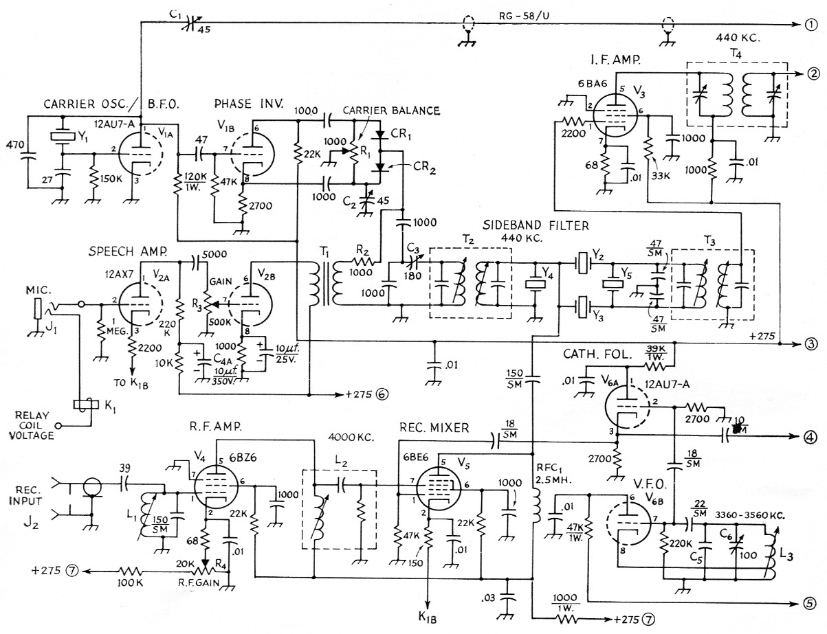
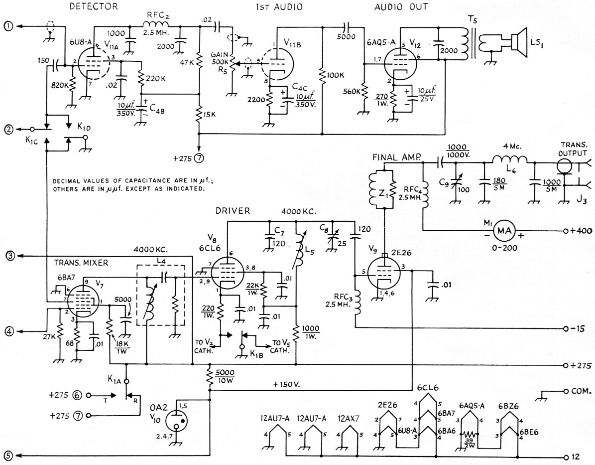
Fig. 2. Schematic diagram of the transceiver. The contacts of Kt are shown in "receive" position. A 12 volt filament hookup is shown; if 6 volts is available, the heaters can be wired in conventional fashion and the 39 ohm resistor eliminated. Resistances are in ohms, and resistors are ½ watt unless otherwise indicated. Capacitors marked "SM" are silver mica; those marked with polarity are electrolytic; all others are disk ceramic, except as specified below.
| C1,C2 | 7-45 pF ceramic trimmer, neg. temp. coef. (Centralab 822-BN). |
| C3 | 9-180 pF mica trimmer. |
| C4 | 10/10/10 µF 350 V triple-section electrolytic (Cornell Dubilier CO210). |
| C5 | App. 600 pF, silver mica (see text). |
| C6 | 100 pF air variable, double-bearing (similar to Johnson 100L15). |
| C7 | App. 120 pF, mica (see text). |
| C8 | 25 pF air variable (Hammarlund APC-25-C). |
| C9 | 100 pF air variable (Hammarlund HF-100). |
| CR1,CR2 | germanium diodes, 1N35 matched pair or separate 1N34s. |
| J1 | 3 conductor microphone jack. |
| J2,J3 | Coax receptacle (S0-239). |
| K1 | 4 p.d.t. relay with coil to match control voltage available (Potter 8, Brumfield GA17 series or similar). |
| L1,L5 | App. 45 turns No. 30 enam. close-wound on ¾ inch diam. iron slug-tuned form (CTC LS-3 or similar). L5 adjusted to desired range; see text. |
| L2,L4 | 4.5 Mc TV sound i.f. coil assembly (Meissner 17-1071). |
| L3 | App. 12 turns No. 20 enam. close-wound on ¾ inch diam. iron slug-tuned form (National XR-72), tapped 4 turns from ground end. See text. |
| L6 | 22 turns No. 24 tinned, 1 inch diam., 11/16 inch long (B & W Miniductor No. 3016). |
| LS1 | Externally mounted speaker, any size. |
| M1 | 0-200 mA d.c. meter. |
| R1 | 1000 ohm control, linear taper. |
| R2 | 1000 ohm, ½ watt. |
| R3,R5 | 500 kΩ control, audio taper. |
| R4 | 20 kΩ, 2 watt wire-wound control, linear taper. |
| RFC1,RFC2,RFC3 | 2.5 mH, 75 mA. (National R-50 or similar). |
| RFC4 | 2.5 mH, 125 mA. (National R-100U or similar). |
| T1 | Plate-to-line audio transformer, approx. 20,000 ohm to 500-600 ohm (Stoncor A-3250, ARC-5 receiver output or similar). |
| T2,T3 | 455 kc slug-tuned i.f. input transformer (Miller 12-C1). |
| T4 | 455 kc trimmer-tuned i.f. output transformer (Miller 112-C4). |
| T5 | Output transformer, approx. 5000 ohm to voice coil. |
| Y1-Y5, inc. | FT-241-A surplus, approx. 450 kc See text. |
| Z1 | 6 turns No. 18 tinned spaced wire diameter on 47 ohm 2 watt resistor (may not be required; see text). |
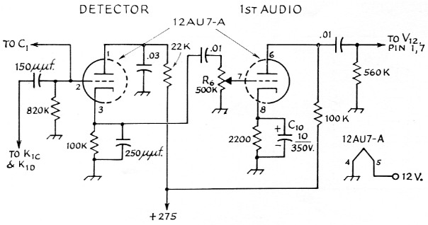
Fig. 3. Circuit of an infinite impedance detector and first audio stage which can be used in place of V11 in Fig. 2. Resistances are in ohm; fixed resistors are ½ watt, and R6 is a 500 kΩ control with audio taper. Capacitances are in µF unless otherwise indicated; C10 is electrolytic (same as C4C, Fig. 2); other capacitors are disk ceramic.
The triode section of the 6U8 (or one section of the 12AU7) is used as the first audio stage. The only precaution here is to shield the volumecontrol lines. The audio output stage, a 6AQ5, gives more than adequate volume. The speaker used with the original rig is mounted in the power-supply unit.
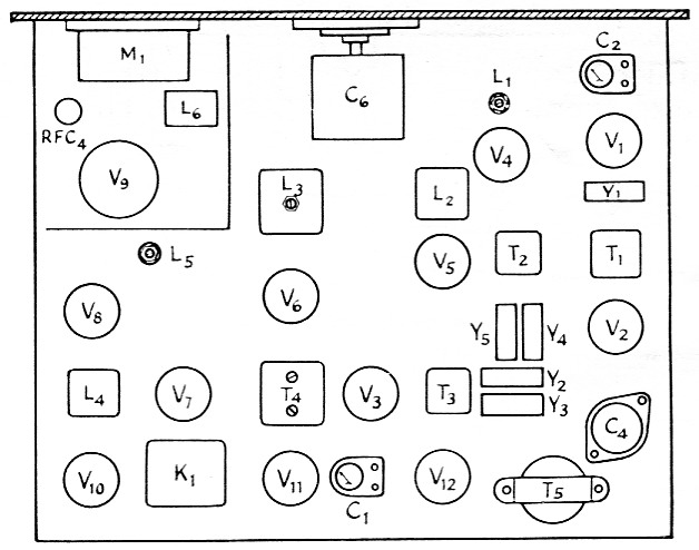
Fig. 4. Layout of the transceiver chassis looking from the top. Chassis size is 10 by 12 inch.
Construction
The chassis and cabinet were homemade as shown in Fig. 5. A standard utility box or cabinet could be substituted if you don't mind increasing the over-all size somewhat. If you are ambitious you will want to perforate the top, so tape a piece of graph paper on the top panel, punch the centers and get on with the job. The top on the rig shown has 448 holes! When all drilling has been completed and the aluminum sections have been cut out and bent to shape, they should be etched in a lye bath and washed with plenty of water. Then clean the pieces off with alcohol, put on decals and spray the outer surfaces with clear plastic.
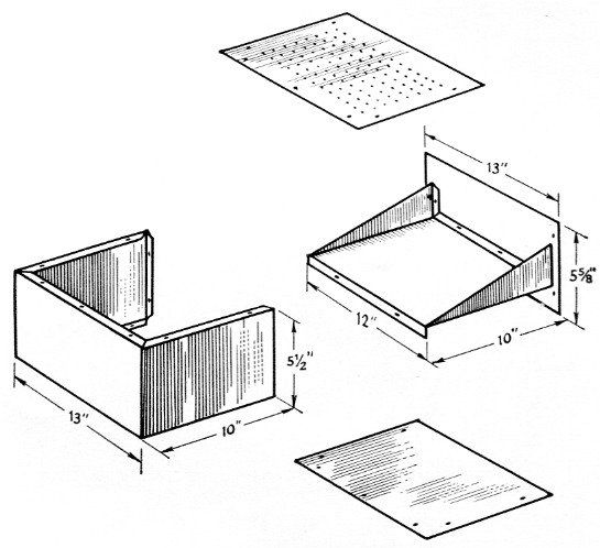
Fig. 5. Exploded view of the homemade chassis and cabinet used by K5BUQ. The chassis, front panel, and top and bottom plates are 0.051 inch aluminum, and the back cover on the left is 0.040 inch stock.
This below-chassis view shows that the small components are readily accessible. Baffle shields help in reducing coupling between circuits that might have a tendency toward setting up self-oscillation.
After laying out the components and punching the chassis and panel, the best place to start wiring is the v.f.o. After it is working properly the receiver section is put together and debugged. This gives an opportunity for preliminary alignment of the filter. The carrier generator and balanced modulator should be wired next, and the b.f.o. injection wired to the detector. At this point the receiver can be aligned for copying sideband.
Before adjusting the filter, I would suggest you consult Single Sideband for the Radio Amateur for much better instructions than I can give here. Don't be disappointed if the filter doesn't do very well at first, for it takes a good deal of practice to really know what you are trying to achieve. If, however, you can get the receiver sounding good and passing only one sideband, that is also about how your transmitted signal will be.
The next trick is to make the transmitter work. Since the oscillator and balanced modulator are already completed, wire the audio, run this and the balanced modulator output through the filter, and check the 440 kc sideband signal. Now couple the v.f.o. to the transmitter mixer, and a 75 meter sideband signal should be realized. The driver and final amplifier stages are then wired and checked out.
After the receiver and transmitter each work by themselves, the switching relay should be wired in and the final de-bugging should take place. (If you are lucky, not over half the stages will be oscillating!) Since each stage is wired and tested separately, there is no big final "smoke test." The final alignment is merely a touch-up of the preliminary alignment.
Houston Taylor, Jr, K5BUQ.