Multiband antennas using loading coils
Two-band operation can be obtained by using plain loading coils, with considerable constructional simplification as compared with the equivalent trap arrangement. This article discusses the principle, and gives dimensions for several 3.5-7 Mc combinations.
Many amateurs operate from locations at which it is impossible to put up a full-length doublet antenna for 80 meter. A doublet antenna can be shortened as much as desired by the use of loading coils. The effect of loading coils is discussed very completely, with graphs and formulas, in Bureau of Standards Circular C74, Radio Instruments and Measurements, published in 1924 and reprinted in 1937. (Many an old-timer in radio will remember this as a standard reference book back in the '20s and '30s.) It is shown that in addition to decreasing the natural frequency of an antenna, the use of loading coils results in the fact that " the harmonic frequencies are no longer integral multiples of the fundamental as in the case of the simple antenna." In Fig. 62, page 76 of the Circular, a graph shows how the next higher resonant frequency differs from the fundamental in one particular setup.
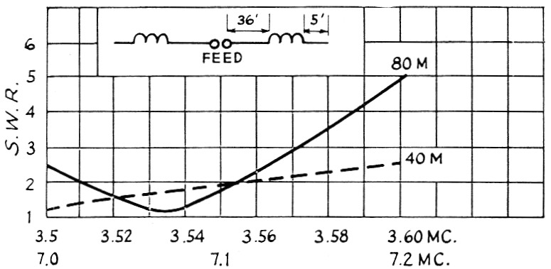
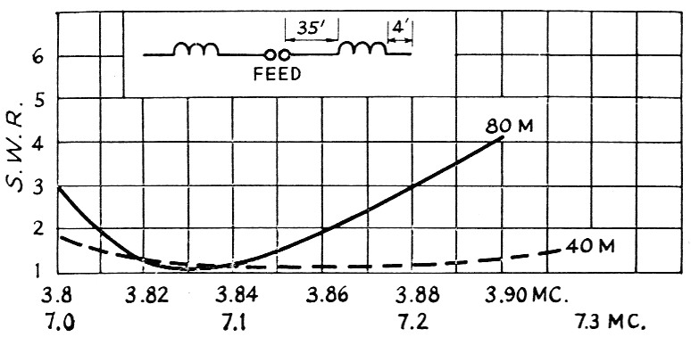
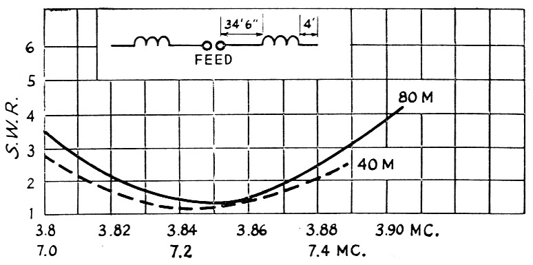
Fig. 1-3, inclusive-Three two-band antenna configurations using 120 µH loading coils, showing effect of small variations in the lengths of the straight portions of the antenna. Dimensions and construction of the sides to the left of the feed terminals are identical with those shown to the right. Standing-wave ratio measurements made with RG-8/U cable (52 ohms) and Micromatch.
An antenna for 80 and 40 meters was made up according to this principle. A few trials with various values of loading inductance indicated experimentally that with 120-microhenry coils placed as shown in Fig. 1, resonance occurred near the lower ends of both bands. With a small change in lengths, as shown in Fig. 2, an antenna which resonated higher in both bands was obtained. Another small change in lengths - resulted in the antenna shown in Fig. 3, which is more satisfactory for phone operation. This antenna is 77 feet long, plus the lengths of the coils and insulators.
The coils were close-wound with No. 18 Nyclad wire on bakelite tubing % inch in outside diameter, 14 inches long. A winding length of 12 inches was used. These coils measured approximately 120 µh. Some other coils were tried, 80 zh. being the lowest value. Resonance in both bands was again obtained but with longer lengths of wire. If the inductance of the coils is too low, the resonance at 40 meters may be too high in frequency, although the 80-meter resonance can be gotten with longer lengths of wire on the ends. With various values of coils and lengths of wire, antennas can be made for 80 and 20, 80 and 15, 80 and 10, 40 and 20, and similar combinations.
As an antenna is made shorter it has sharper resonance. This may not be too much of a handicap for hams who operate over only 100 kc. or so in the 80-meter band, as many s.s.b. addicts do. The antenna of Fig. 3 is actually just slightly longer than a regular doublet at 40 meters, up to the loading coils, and can be operated over the entire 40-meter band with a fairly low s.w.r. on the feeder. The advantage is two-band operation with an antenna 77 feet long without traps.
This antenna has been used on the air for several years and the reports have always been just about the same as those obtained with regular doublets. Obviously the loading coils should be made as low-loss as possible by using good insulation and as large wire as is practical. There are no capacitors to break down as in traps, and the 120-µh. coils have been used with a kilowatt transmitter input with no difficulty.
We have not found any exact formulas to determine the relationship between the lengths of wire, loading coils, and the two frequencies. The antennas are very simple to adjust with a grid-dip meter coupled to a single-turn loop connected to the feed terminals, as quite small changes in the wire lengths result in appreciable changes in resonant frequencies.
This principle can be extended; that is, by using two sets of coils, operation on three frequencies is possible, on four frequencies with three sets of coils, and so on. However, these get very complicated to adjust, since the second set of loading coils changes operation of the first set somewhat, and the adjustment process gets rather tedious.
William J. Lattin, W4JRW.