More sock-for-cents antenna
Every ham seems to have a favorite band, whose virtues he extolls with solemn dedication and intense conviction. Regardless of what your favorite amateur band is, however, you must admit that the bands tend to become more and more crowded; and at times the resulting QRM can reach the distressing proportions of a head-shattering crescendo, particularly on the lower bands. It is somewhat disappointing to find that the usually imaginative and resourceful ham has somehow failed to provide the obvious solution demanded by the situation: greatly improved, inexpensive, easy-to-construct antennas. Some greatly improved antennas have been designed; but they are, unfortunately, expensive and/or difficult to construct. Most hams today are inclined to run down to the local amateur radio supply store and purchase a commercial kit whenever they have need for an antenna, instead of putting real thought and effort into designing something really worthy of our fine hobby. In case you have forgotten, OM, one of the reasons the FCC granted you that call was for the " ... extension of the amateur's proven ability to contribute to the advancement of the radio art." (§12.0)
A moment of reflection upon some technical aspects of antenna information reveals some worth-while facts. As any ham worth his ticket knows, a decibel (dB) is a unit used to indicate the relative loudness of signal strength. A gain of 6 dB is equivalent to increasing the power factor by 4. Thus, an antenna with a 6 dB gain would cause a 75 watt signal to assume the authority of a 300 watter; a 10 dB gain would make the 75 watter kick out a signal like a 750 watter! And - get this! - a 20 dB gain would give the little 75 watter a signal comparable to a 7500 watt station! - and it's legal, because your input would be a legal 75 watts! If you have a General License and wanted to run a full 1000 watt, your commanding signal would, of course, be comparable to a 100,000 watt station! Obviously, the practical answer to the relentless search for more "signal sock" is a better antenna installation. We shall, therefore, present a rewarding little project that can be completed in about an hour some Saturday afternoon while the XYL goes downtown to do a bit of lastminute week-end shopping. Even if you, like we, have a below-average junk box, you'll get more sock for cents with the antenna system described here.
Fig. 1 illustrates the More-Sock-for-Cents Antenna. At first glance, some skeptics are apt to growl impatiently, "Nothing but a halfwave dipole!" Such a cynical attitude of disparagement is going to mellow into keen interest when the antenna is given a bit more study. But let's begin at the beginning.
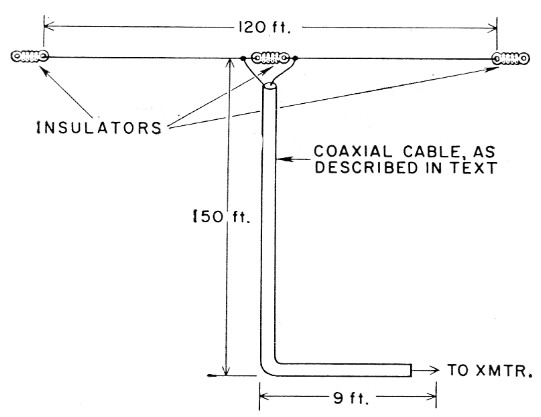
Fig. 1. The author's antenna.
The antenna is cut for your favorite frequency by using the formula:
![]()
Since we like the friendly, intimate contacts of 75 phone, we decided upon an antenna resonant at 3900 kc, the middle of the 75 meter phone band.
Good quality antenna wire is an absolute necessity for a superior antenna. It just stands to reason; the more suitable the antenna wire, the more suitable the antenna. Here at WA2FQZ, we happened to stumble upon 279 feet of 75-ohm RG-144U coaxial cable coiled up in a corner of the junk box; so we just stripped 120 feet of it and used the center-conductor section for the antenna. The center-conductor section is silver-coated copperweld and thus provides a mechanically strong, electrically efficient radiator. Furthermore, this wire is very appropriate because the length/diameter ratio results in a rather low Q. This means, of course, a broad response that is especially good for QSYing.
It is strongly urged that you use an additional 159 feet of RG-144U as feed line, which length, incidentally, avoids exact resonance at all frequencies in all amateur bands. It should be found that the 75-ohm RG-144U, which has a velocity factor of .695, provides an exceptionally fine match to the impedance of the antenna. Nine feet of the feed line is allowed to run from the transmitter to the nearest window or feed-through point. The remaining 150 feet, as you will be pleasantly surprised to learn, will go straight up to the center feed-point of the antenna.
At this point in the construction of the antenna, we found our usually reliable junk box had been depleted of solder. So we made the only cash expenditure necessary in assembling this antenna: we bought 250 worth of solder at the local solder shop.
So that's it! MORE SOCK FOR CENTS!
Ridiculously simple, isn't it? Proof once again of the fabulous innovations that can result from a little perseverance and that ubiquitous Aladdin's lamp of ham radio: the junk box!
James F. van Detta, WA2FQZ.