Low-pass filter for 6 meter operation
Effective network offering benefit in both transmitting and receiving.
The filter described in this article not only does a good job in suppressing TVI from harmonics generated in the low-frequency stages of a 50 Mc exciter, but it will also eliminate spurious signals from a near-by Channel 2 transmitter which often clutter up the band on a 6 meter receiver. It is equally effective in suppressing harmonics from transmitters operating on any of the lower-frequency bands.
A ham operating in the 6-meter band may be faced with several problems relating to television. The fundamental of his transmitter carrier may overload stages in neighboring TV receivers tuned to Channel 2. Various harmonics of lower frequencies in the oscillator or multiplier stages of his transmitter may fall in one or more of the v.h.f. TV channels. A third difficulty may come up if the ham station happens to be located not far from a Channel 2 transmitter. In such a situation, the ham may find the 6 meter band cluttered with sync buzzes and distorted sound.
Solving the TV receiver overload problem is, of course, a matter of inducing the TV viewer to install a 300 ohm high-pass filter in his TV receiver. A low-pass filter in the feed line of the 6 meter antenna is not only useful in suppressing harmonic output from the transmitter, but is also very effective in suppressing Channel 2 sync buzzes. Before installing the filter to be described, these buzzes were bothersome as far down as 49 Mc on the author's 6 meter converter.
Values for the low-pass filter whose diagram appears in Fig. 1 were worked out using the m-derived and constant-k equations from the ARRL Handbook. The characteristics are shown in Fig. 2. The filter was designed with a cutoff frequency at 54 Mc. and a frequency of infinite attenuation at 55.25 Mc, which is the Channel 2 picture-carrier frequency.
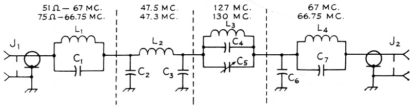
Fig. 1. Circuit of the 6-meter low-pass filter. See text referring to resonant frequencies. See table on following page for values of inductance and capacitance. For transmitter inputs of 20 watt or less, 600 volt 2 % zero-temperaturecoefficient ceramic capacitors (Centralab type Ta) are suitable for all fixed capacitors; for higher power 6000 volt disk capacitors (Centralab DD60), Sprague 60GA, Erie HD6 or similar) should be used. C5 is a 45 pF negative-temperature-coefficient ceramic trimmer (Centralab 822BN), J1 and J2 are chassis-mounting coax receptacles (S0-239).
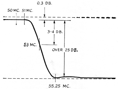
Fig. 2. Frequency characteristic of the filter circuit shown in Fig. 1.
The filter passes signals up to 51 Mc with only about a 0.3 to 0.5 dB loss, and attenuates the Channel 2 picture carrier, and other signals on Channel 2 and above, up to over 30 dB. Insertion of the filter in the transmission line at K9ARA caused negligible change in the v.s.w.r. and a v.s.w.r. of less than 1.5 was obtained up to 51 Mc. Both 51 and 75 ohm models have been built and used.
Construction
The material cost of the filter is approximately $5.00, with the case and connectors being the most expensive items. For transmitters of over 20 watt input, 6000 V 20 % disk ceramic capacitors were used with no difficulties. One filter was used successfully with a 300 watt input transmitter on 6 meter. The filter, of course, can be used also on the lower-frequency bands.
The photos show the construction in a 5 × 2¼ × 2¼ inch Minibox. The coils are supported by the coax connectors and by the short capacitor leads, one of which is soldered to a ground lug. The only stand-off insulators used were the two vertical, single-lug terminal strips which support the trimmer capacitor and its parallel coil and fixed capacitor. For high powers, ceramic standoffs will prevent possible insulation breakdown. Leads should be centered in the middle of the holes through the shields and excess solder resin cleaned from capacitor bodies and stand-off insulators.
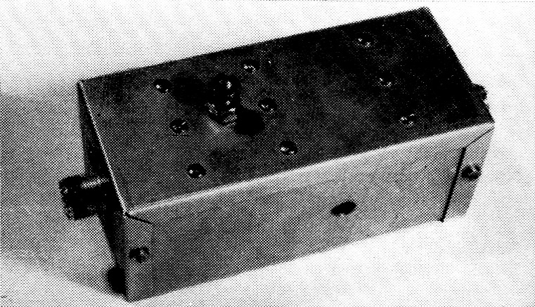
The low-pass filter is enclosed in an aluminum box measuring 2¼ inch square and 5 inch long. The terminal on top is for the ground connection. The hole in the side provides access to the trimmer capacitor, C5.
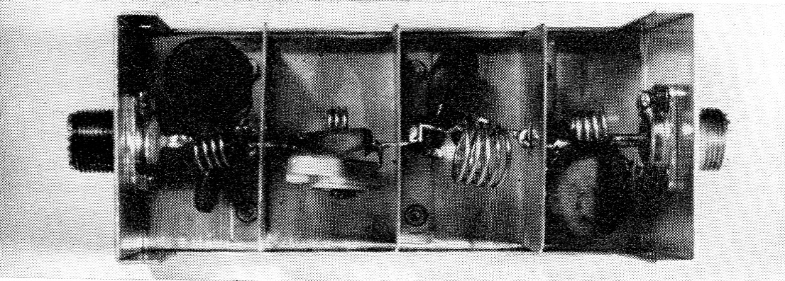
Connections between the various sections of the filter are made through 5/16 inch clearance holes cut in the centers of the shielding partitions.
A 10-32 screw was put on the side of the filter case to attach a suitable ground wire. A ¼ inch-diameter hole was drilled in the case to admit the tuning tool for a final adjustment with the cover on.
Adjustment
Before the sections are connected together permanently, the coils are preadjusted individually with a g.d.o. to resonate at the frequencies indicated with associated capacitors as follows: L1-C1; L2-C2-C3; L3-C3-C6; L4-C7. Note that C3 is common to both the L2 and L3 circuits. C5 is not connected at this juncture. Coil turns are spread apart or squeezed closer together in adjusting to the resonant frequencies indicated in Fig. 1, which are not too critical. The sections are then all connected together, C5 is added and the final filter adjustment is made with this trimmer capacitor.
Proper operation of the filter requires that the trimmer capacitor C5 adjust the frequency of maximum attenuation to 55.25 Mc. This can be done by using a signal from a Channel 2 TV station, a converter capable of tuning to 55.25 Mc, and a general-coverage receiver equipped with an S meter. For the usual converter with 20-meter (14-18 Mc) i.f. output, the receiver would be tuned to 19.25 Mc. The trimmer capacitor, C5, is then adjusted for a minimum S-meter reading on the TV signal. A definite null should be tuned through with the capacitor. If the null occurs with a maximum or minimum capacitor setting, the turns of L3 can be spread out or squeezed closer together.
The author used the sweep setup shown in Fig. 3A for checking filters. An accurately-calibrated 55.25 Mc marker is loosely coupled to the crystal-diode r.f. probe shown in B. The maximum-attenuation notch was adjusted to 55.25 Mc. by means of the trimmer capacitor in the filter. Incorrect setting of the trimmer will attenuate 6 meter signals around 51 Mc, or will reduce the attenuation characteristics of the filter on Channel 2.
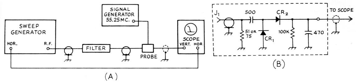
Fig. 3. (A) Setup for checking filter response.
(B) Circuit of the diode r.f. probe. Capacitances are in pF and capacitors are disk or tubular ceramic. Resistances are in ohms and resistors V2 watt. CR1 and CR2 are 1N67A, 1N34A, 1N56A or similar. J1 is a coax receptacle. Input resistance value should match coax line which should be 50 or 75 ohm, depending upon filter design impedance. The signal generator is coupled to the probe by looping the end of the generator output wire around the probe input resistor. The trimmer capacitor in the filter should be adjusted for minimum response at 55.25 Mc.
Precautions
The filter can be placed just outside the coaxial antenna relay if both converter overloading and transmitter harmonics are a problem, or it can be placed in the line close to the transmitter if only transmitter-harmonic reduction is needed.
The v.s.w.r. of the antenna, transmission line, transmit-receive switch, and connecting cables to the transmitter should be measured with and without the filter, using a v.s.w.r. bridge. Without the filter, the v.s.w.r. should be less than 2, and preferably less than 1.5, to avoid excessive filter losses or possible damage to the filter components at high powers. Readjusting the antenna match, eliminating cable splices and odd types of interconnecting cable will minimize the v.s.w.r. that the filter and transmitter will see.
If the v.s.w.r. is higher after the filter is in serted, reduce the transmission-line length one or two feet at a time, noting the length at which a minimum v.s.w.r. is obtained, and recording the inches of line removed. If the cable is cut too short by accident, the next optimum length will be half cable wavelength toward the antenna from the missed point (77 inches for a frequency of 50.5 Mc.). Another optimum point will be 77 inches back and this difference could be made up by increasing the length of the line section connecting the transmitter to coaxial relay. A change in the apparent v.s.w.r. when the filter is inserted may indicate that the transmitter has high harmonic output and the filter is just doing its job.(1)
Notes
- This may also be a result of parallel transmission-line current as discussed in the ARRL Antenna Book. - Ed.
John R. Lange, K9ARA.