Construction techniques
Some tips for the novice on building gear.
The newcomer to ham radio is faced with the problem of whether to buy ready-built radio gear or build his own. If the beginner is anxious to learn something about the technicalside of radio, there is no better approach than by building equipment and learning how it works. In this article the right and wrong ways of construction will be discussed with the end view of showing the Novice how to build a piece of equipment and have it work the way it should.
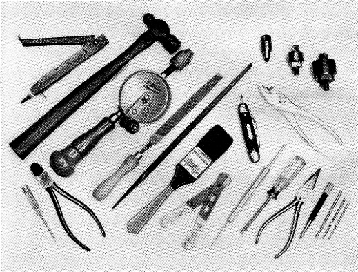
Here are some of the tools mentioned in the text. The tool between the knife and screwdriver is a soldering aid, which has a probe at one end and a fork at the other. This is a handy gadget for feeding wires through terminals and for use in other soldering operations. The tool at the upper left next to the hammer is a nibbler tool.
What tools do you need?
Naturally, if you plan on doing your own construction work, there are certain tools you'll need. The basic tools required are listed in Table I. With these tools you should be able to do all the cutting and drilling required to prepare a chassis for wiring. You'll note that no particular type of soldering iron is specified in the table. If you are only going to do an occasional job, a soldering gun might be your best bet. A soldering gun must be turned on for each soldering operation, but it only takes seconds to reach soldering temperature. Some amateurs prefer a constantheat-type iron. If you prefer the constant-heat type, get one with a 60-watt rating and a 1/1-inch tip. Also, this type is lighter and easier to handle.
You can get by with an adjustable hole cutter for making socket holes, but socket punches do a neater and quicker job. Three are required, one each for 7- and 9-pin miniature, and another for octal sockets. For cutting large holes, such as for transformers, the nibbler tool is very handy.
Don't abuse your tools by using them for jobs they were not intended for. A little time and effort keeping drills sharpened and oiled will keep the tools in good shape. An oil stone can be used to touch up the cutting edges of drills. If the cutting edges of tools get too dull to be touched up with a stone, then they should be sharpened on a grinding wheel. If you use a grinding wheel to sharpen drills, keep the same cutting angles on the face of the drill. If you can afford one, an electric drill is a real work saver and there are many different types of attachments available that will make your work easier.
| Long-nosed pliers, 6 inch. |
| Diagonal cutting pliers, 5 inch. |
| Screwdriver, 6- to 7-inch, ¼ inch blade. |
| Screwdriver, 4- to 5-inch, 1/8 inch blade. |
| Hand drill, ¼ inch chuck. |
| Metal working drills, 3/8 and ¼ inch, and Nos. 18, 28, and 33. |
| Slip-joint pliers, 6-inch. |
| Large coarse files, one flat, 12 inch, one rattail, 3/8 inch diameter. |
| Small files, one flat, 8 inch, one rattail, ¼ inch diameter. |
| Hacksaw for 10 to 12 inch blades. |
| Pocketknife. |
| Square and straightedge. |
| Hammer, small ball-peen type. |
| Chisel, ½ inch face. |
| Center punch, 3 or 4 inch. |
| Socket punches, one for 5/8, ¾, and 1_1/8 inch holes. |
| Soldering iron (See text). |
| Resin-core solder. |
| Optional tools: |
|---|
| Nibbler tool. |
| Electric drill, ¼ inch chuck. |
| Wire strippers. |
| Reamer, point 1/8 inch diameter, shank ½ inch. |
| Soldering aid. |
| Hex nut driver set, hex sizes 5/16, ¼, 5/16, 22/32, 3/8, and 7/16 inch. |
| Bench vise, 3 to 4 inch jaws. |
How to lay out a chassis
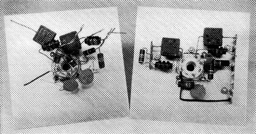
The right and wrong ways of wiring components around a tube socket. Note at the right how the components are neatly arranged around the socket and are not "piled up." It may be argued that the circuit at the left will work just as well, but this is not true. There is always the danger of unnecessary coupling between the input and output side of the circuit, which is usually undesirable. In addition, one can quickly see that it would be much easier to check the wiring at the right than at the left.
If you are going to build a piece of gear from an article, it is always best to follow the layout of the unit described as closely as possible. In many cases the writer of the article will state that the layout isn't critical, but this usually means the general layout should be followed, even though an exact duplicate isn't necessary. Don't just grab a drill and start drilling holes - give a little time and thought to the arrangement of the components. Incidentally, aluminum chassis should be used wherever possible as aluminum is much easier to work with than steel. However, for heavy power supplies, steel chassis will provide greater support.
When you buy the chassis you'll find that it is covered with paper. Leave the paper on the chassis, since it will protect the top from unnecessary scratches when doing your layout. All the components that are to be mounted on the top of the chassis should be assembled and arranged on the top for the best layout. Be sure that parts below deck don't interfere with the top-mounted components. If the unit is to fit inside a cabinet, allow enough room around the parts to clear the cabinet sides when placed inside.
In laying out the components, make the electrical circuit follow a logical sequence. In other words, if you have a transmitter of three stages, oscillator-buffer-amplifier, you wouldn't put the oscillator on one side, the amplifier in the middle, and the buffer on the far side. Also, when mounting tube sockets, give some thought to the pin arrangement. Wherever possible, the plate connections of one stage should face the grid connections of the next stage. As a general rule, any coil should be mounted at least its own diameter away from surrounding metal, panels or chassis sides. This is particularly necessary if a steel chassis is used. If the coils are mounted too close to the metal, the Q of the coil is degraded.
After you've decided on a component arrangement, you are ready to mark the chassis for drilling of holes. You'll find a square and straightedge handy for this purpose. Leave the paper on the chassis top and mark off the hole arrangement with a pencil. Wherever a hole is to be drilled, use the center punch and hammer to mark the spot. The center punch will make an indentation in the chassis which will keep your drill from wandering when you drill the hole. After all the holes are drilled, you can remove the paper.
Next, remove all burrs from around the holes. For small holes you can used a larger size drill to remove the burrs. With larger holes, either a knife or a cold chisel will do the job. If you are not fussy about the appearance of the completed unit, you can now mount the components. However, a much neater and cleaner piece of gear will result if the chassis is first prepared properly. There are two methods of preparing aluminum so that the finished product has a smooth sheen. The chassis can be buffed down with steel wool, washed to remove oil, and then sprayed with a clear acrylic spray. The sprayed chassis will resist finger marks and dirt when you handle the unit. The other method consists of preparing a lye bath with ordinary household lye. The lye should be mixed in an enameled container such as a dishpan or baby's bathtub (remove any dishes or babies, first.) Use about ¼ to ½ can of lye to each gallon of water and be careful not to get the solution on your hands or clothes. The aluminum chassis is then immersed in the lye bath for ½ to 2 hours, depending on how strong a solution you have. It is a good idea to use a test piece of aluminum first. When the chassis is covered, you'll notice the solution will bubble, so ventilation should be provided to permit the generated gas to escape. After the chassis has been in the solution long enough, remove and wash it clean with cold water. A paint brush wet with water can be used to remove the black oxide which often forms. After a thorough wash, let the chassis dry and then give it several coats of clear acrylic spray. It is now ready for the components.
Wiring do's and don't's
There are many types of hookup wire available and the beginner is sometimes in a quandary as to which type to use. Whichever type is used, consideration should be given the amount of current the wire will be required to carry and the voltage its insulation must stand without breaking down. A wire with 1000-volt insulation commonly used is Belden type 8350 thermoplastic hookup wire (No. 22 conductor). For heater circuits where the current does not exceed 2 amperes or so, No. 20 solid tinned wire is adequate. Where greater current-carrying capabilities are required, No. 18 or larger wire can be used. If you have any doubts about the current-carrying capabilities of a particular wire size, look up its circular-mil area in the wire table in the ARRL Handbook and allow about 500 c.m. per ampere.
If TVI is likely to be a problem, shielded wire should be used for all heater wiring and leads not carrying r.f. currents. Belden 8885 shielded wire, which has a conductor the equivalent of No. 20, is suitable for most applications. Coax cable can be used for high-voltage leads (over 1000 volts) that must be shielded. In the event stranded hookup wire is used, the ends should first be twisted together and tinned with solder. Otherwise, when the wire is fed through a terminal there is always the danger of a single strand of wire getting loose and shorting to another terminal or ground.
Before getting into the story of making connections and wiring, a word about soldering is in order. Probably the place where most beginners make mistakes is in their soldering. In the first place, the soldering iron should be hot enough to deliver sufficient heat. The tip of the iron should be clean, bright metal. If the tip is pitted or scaly, as it will become through continued use, it should be filed clean. When the tip is clean, heat the iron and flow some solder on the tip and then wipe it clean. This tins the iron and prepares it for soldering. In radio work always use a noncorrosive solder. When you buy solder be sure to specify a resin-core type. A 40 per cent tin/60 per cent lead content is satisfactory for radio work. If you're working on etched circuit boards or with any unit that cannot stand too much heat, it would be wise to use solder with a higher tin content as the melting point of such solder is lower.
The process of soldering is quite simple. Apply the tip of the iron to the work and let the work get hot enough to melt the solder. Don't put the solder on the iron tip, but apply it to the connection. When the connection reaches soldering temperature, the solder will melt and flow around the connection.
If the work isn't hot enough, or if the solder is applied to the iron and not the work, a "cold" solder connection is likely to result. A cold solder joint is one that looks good but can cause you a lot of grief. The connection may prove to be intermittent, which makes it difficult to locate if you have to do any trouble-shooting. Also, be sure that all the leads being soldered are clean. In fact, it may take a little more time but it is a good idea to tin all leads with solder before putting them in a terminal. If you want, you can run the lead through the terminal and wrap it around. The only trouble with the "wrap-around" system is that you may have to remove the lead when trouble-shooting, and the connection can get quite messy. A simpler system, and just as good from the standpoint of making a solid electrical connection, is to run the lead through the terminal, make a 45-degree bend on the end of the wire so it doesn't slip out of the terminal, and then solder it in place. When you have several leads going into a single terminal, make sure that all of them get soldered. If you tin the leads beforehand, you shouldn't have any trouble getting a good soldered connection. Don't hurry your soldering work. A little time spent making good connections can save you a lot of work later on.
When you come to the actual wiring of the unit, run all wires, wherever possible, parallel with the chassis sides. This is also true of small components such as resistors, capacitors, and coils. The completed unit will have that "commercial" look, but what is more important, will be much easier to service than if you have a hodgepodge of wiring. All leads carrying r.f. should be as direct as possible and should not wander around the chassis. On the other hand, leads not carrying r.f. can be routed around the edges of the chassis. In this case, you will probably find that you have several leads running parallel with each other and the unit can be made to look neater by cabling the leads or taping them together at intervals. Cabling techniques are described in detail in the ARRL Handbook. The liberal use of bakelite tie points and ground lugs will make your job easier and improve the appearance of the equipment.
Holes large enough to clear Nos. 4, 6, and 8 machine screws can be drilled with Nos. 33, 28, and 18 drills, respectively. Most volume controls require a 3/8 inch diameter hole and toggle switches a 15/32 inch hole. Miniature tube socket mounting frame holes are slightly smaller than a No. 4 screw, so the holes should be drilled out to take a No. 4 screw. When mounting any component with screws and nuts, always use lock washers, otherwise the component is liable to work loose.
What to wire first
Usually the best approach is to wire the heaters and power supply first. By doing this, you can test the supply and heaters before going on to the other wiring. Wherever possible, mount resistors and capacitors close to but not directly over a tube socket. If you pile all the components directly over the socket you'll find it hard to make connections and difficult to check socket voltages. When soldering germanium diodes, small resistors or disk capacitors, especially if the leads are short, hold the lead being soldered with a pair of pliers between the body of the component and the connection. This will prevent too much heat from reaching the component and ruining it. Wherever leads pass through holes in the chassis, use a rubber grommet to prevent the lead from chafing or shorting out. If the circuit calls for grounding terminals on a tube socket, mount a ground lug under the screw and nut holding the socket and make your ground connections to the lug. In other words, keep the leads short.
When the unit is completed, there are a couple of things you can do to test it before actually applying power. If you have an ohmmeter, check the resistance between the +B line and chassis ground.
Look at the circuit diagram and find out the value of the bleeder resistor in the power supply. If there are no other resistors connected between the +B line and ground, then your ohmmeter should read approximately the same value as the bleeder. Where there are other resistors in parallel with the bleeder, such as voltage dividers, these values must be taken into consideration also. You can use Ohm's Law for parallel or series resistors for an exact figure. However, with nearly all circuits Novices will be using, the resistance between +B and ground should be something more than, say, 20,000 ohms. The ohmmeter should read whatever value the +B line should be above ground. If it is a much lower value than this, it is a good idea to check your wiring for errors. Otherwise, you will be blowing fuses or ruining the power supply when you turn the unit on. By using the ohmmeter, you can also follow the circuit, making resistance and continuity checks. If you come across a reading that doesn't look right, check over your wiring. These precautions can sometimes save you the cost of expensive components.
While it is understandable that a Novice is in a hurry to get a piece of gear completed and on the air, a little more time and effort in building your gear will pay handsome dividends.
In addition to the information given in this article, it is suggested the beginner study the construction practices chapter of the ARRL Handbook. You'll find information on color codes, how to wire coax fittings, and many other things of interest to the ham who wants to "roll his own."
Lewis G. McCoy, W1ICP.