A complete two-band station for the V.H.F. beginner 1 - A simple tuner for use with converters
An efficient layout for 50 and 144 Mc. Entirely home-built.
This complete station for 6 and 2 is not the cheapest way to set up for v.h.f. business, but in quality and versatility it is way ahead of what the same expenditure would buy in ready-made gear. Built in simple subassemblies that plug together directly or through cables, it can be a long-term project if your finances and spare time make this desirable. Build it for one band, at first, or make whichever portion of the station you need most. Though the equipment is labeled and described for the beginner, we have a feeling that a good many v.h.f. men who have been around a while will find it of interest, too. Our cover this month shows all the units for both bands. Subsequent issues of QST will describe all of these units.
Buy or build? This question faces every new amateur, and it is likely to remain with him as he advances in the art. Buying is the quick and often easy way to get started in amateur radio. There are still sound arguments for building one's own, however, and plenty of hams, new or old, still play the game that way.

First, there is the matter of cost. Admittedly, parts cost money these days, but if the job is done wisely the newcomer can build himself a complete station for much less than similar facilities would cost ready-made. Then, nearly all commercial gear is a compromise in one or more ways. When you roll your own, you can design your station to do what you want it to do, and to look the way you want it to look. You don't pay for anything that you don't need. A transmitter that works from 80 through 6 meters, for example, is a poor investment for the fellow with no interest in anything but v.h.f. work. It's a sure thing that a v.h.f.-only rig will deliver a lot more 6-meter watts per dollar than the multiband variety.
But perhaps most important is the nature of the hobby itself. Despite all the easy approaches to it, ham radio is still a technical avocation. The fellow who learns his way around is going to get more out of hamming than the mere purchaser of boxes. When you collect the parts (and perhaps make a few of them), put a station together with your own hands and skill, and make it work to your satisfaction, you have accomplished something. The end result is your station in a way that no commercial package can ever be, and you will be a better ham for having done the job!
Our station was designed to help you start on the v.h.f. bands that way. You may not need to build all of it. If you already have a good communications receiver, you may not be interested in the simple tuner shown here. If you want to work on just 6, or only on 2, the equipment for the band of your choice will do the job just as well as if the station was designed for that band only. Nothing necessary is omitted, and nothing in the way of useless glamour is included. Each unit is intended to do its job well, and to allow for improvement of the station later on.
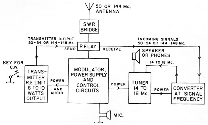
Fig. 1. Block diagram of the two-band v.h.f. station. A central unit contains the speech equipment, power supply and control circuits. The antenna connects to a send-receive relay on the back of this unit through a standing-wave bridge. The transmitter r.f. assemblies for 50 or 144 Mc plug into the left side of the control unit, and a tuner for 14 to 18 Mc (described in this issue) into the right side. Converters for 50 or 144 Mc reception plug into the right side of the tuner. The various units may be interconnected with cables, instead of being plugged together, if operating convenience so dictates.
The transmitter r.f. units are stable and efficient. They include provision for c.w., and may be adapted to variable-frequency control. They will make fine exciters for high power later on. The modulator and power supply use quality components, and are handy items around any ham shack. Control circuits are included, so that the question of how to use the gear in actual communication (so often left unanswered in items supposedly for the beginner) is completely taken care of. The receiving system is a little different from anything you've seen in modern v.h.f. articles, but it does the job. You can receive c.w. with it, as well as a.m. or f.m. phone, and it can even produce readable s.s.b. signals with a bit of care. The converter "front ends" for 50 and 144 Mc. are excellent performers, and if you decide later to use a communications receiver in place of the tuner, they will give you v.h.f. reception second to none.
Last, but by no means least, nearly every v.h.f. station description tells the builder to use a standing-wave bridge in tuning up the transmitter and adjusting the antenna - but few home-built s.w.r. bridges will work on 6 or 2. This station includes a v.h.f. s.w.r. bridge. But enough of the sales talk. Let's get to the business at hand.
The receiving system
Some means of listening is usually the first requirement of the newcomer, so we will consider reception first. It is almost standard practice in v.h.f. circles to employ a converter of some sort, which changes the signal on 50 - 54 Mc or 144 - 148 Mc to some lower frequency before it goes through the detection process. There are several reasons for this, but perhaps the most important is selectivity. It is difficult if not impossible to attain the desired degree of selectivity at 50 Mc. or higher, but the difficulty de creases with frequency. This is the main reason for the use of so-called double-conversion receivers, even on our lower amateur bands.
In a communications receiver, a 14 Mc signal, for example, may be converted to 455 kc or lower, where it is more readily amplified than at the original frequency. In our receiver we convert from 50 or 144 Mc to 14 Mc, and our amplification and detection take place at the latter frequency. This is not quite as good as if it were done in the manner of the communications receiver, which would include a second conversion, but it does have advantages for the home constructor, not the least being simplicity. We can tune 14 to 18 Mc with our little tuner, without the tracking problems that bedevil the designer of a superheterodyne-type 14 Mc receiver, and the whole works involves only a broad-band amplifier, a detector, and a simple audio system. These jobs can be handled easily with three tubes.
Ahead of this we use crystal-controlled converters, which amplify the signal and then convert it to some frequency between 14 and 18 Mc, at which point our tuner takes over. If you decide to go to the communications-receiver method of reception later on (a desirable step if you can afford it), these converters will give you v.h.f. reception of the highest caliber. The simple tuner need not be abandoned, however. It can serve for portable operation, or for use under any circumstances where the ultimate in sensitivity and selectivity are not required.
You can listen on the 14 Mc amateur band, and to various commercial and broadcasting services between the top end of that band and 18 Mc with the tuner, so it makes an interesting project on its own. Consulting the circuit diagram, Fig. 2, it will be seen that the tuner uses two 6CB6s as i.f. amplifier and detector, followed by a two-stage audio amplifier using a 6CX8 triode-pentode. Power is obtained by plugging into the side of the modulator and power supply unit directly, or through a 4-wire cable of any convenient length. If the power supply has not yet been built, the tuner may be tested on any supply capable of delivering 150 to 200 volt d.c., at a few milliamperes, and 6.3 volt a.c. or d.c. at about 1M amperes. A 6-volt car battery and 90 volt of B battery will also handle it, though drain from a B-battery source may be excessive when a converter is added.
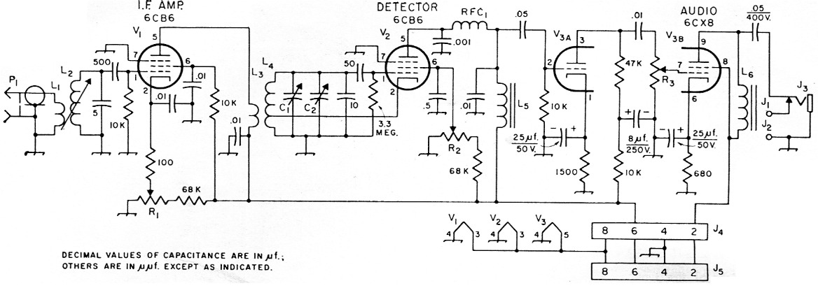
Fig. 2. Circuit diagram and parts information for the 14 to 18 Mc tuner. Capacitors marked with polarity are electrolytic. Others are paper-tubular, ceramic or mica, 200 volt or more, unless marked. The .01 and .001 µF are ceramic disk. Resistances are in ohm, resistors are ½ watt unless specified.
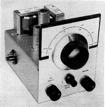
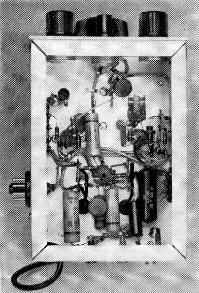
The simple tuner for the v.h.f. station. The tuning range is calibrated for the v.h.f. bands, though the tuner actually covers 14 to 18 Mc. The calibration is drawn on white paper and taped to the area around the vernier dial. Controls below the dial are the i.f. gain at the left, the regeneration at the right, and audio gain, center.
| C1 | 50 pF double-bearing variable (Hammarlund MC-50-S). |
| C2 | 4-30 pF ceramic trimmer (Mallory ST554N or Centralab 822-EN). |
| J1,J2 | Insulated tip jack. |
| J3 | Closed-circuit phone jack. |
| J4 | 8-pin male chassis fitting (Amphenol 86-CP8). Goes on left side of chassis. |
| J5 | Octal socket (Amphenol 77-M1P-8). |
| L1 | 3 turns No. 24 insulated wire wound over low end of L2. |
| L2 | 4½ to 10 µH iron-slug coil (Miller 21A826RB1). |
| L3 | 4 turns No. 24 tinned, 32 t.p.i., ½ inch diam. |
| L4 | 10½ turns like L3. Both are mode from single piece of B & W Miniductor No. 3004. See text. Tap at third turn from inner end. |
| L5,L6 | 16 H 50 mA filter choke (Stancor C-1003). |
| P1 | Shielded phono plug, attached to 18-inch length of small-diameter 52 or 75ohm coaxial cable. |
| R1,R2 | 20 kΩ control (25 kΩ also suitable). |
| R3 | 500 kΩ control, audio taper. |
| RFC1 | 100 µH r.f. choke. |
| V1,V2 | 6CB6. |
| V3 | 6CX8. |
The detector tuning capacitor, C1, is attached to a vernier dial (National Type AM-7). The actual tuning range is from just below 14 to just above 18 Mc., but the white dial scale taped to the front panel shows the equivalent v.h.f. ranges, 50 to 54 and 144 to 148 Mc. The calibrated scales can be added after the receiver is completed, and you have the range where you want it on the dial. Controls below the dial are i.f. gain, left, audio gain, center, and regeneration at the right.
Regeneration is the means by which we achieve a fair measure of performance from so simple a receiver. Three tubes may not seem like much in these days of umpteen-tube chrome-plated monsters, but this receiver is not unlike those that were in general use not too long ago. A regenerative or superregenerative detector is a marvelous device when properly controlled, and with the tubes we have today they can be made to work much better than the blooper receivers our predecessors made out with in the '20s, and even in the '30s. Such a receiver requires a bit of skill and patience in tuning, but when you learn how to ride it, the regenerative detector will take you a long, long way! As a tuner following a crystal-controlled v.h.f. converter, its equal would be hard to find in the low-priced communications receiver category.
The amplifier stage, V1, preceding the detector provides gain, but more important it isolates the detector from the converter stages, and makes control of regeneration a relatively simple matter. The gain control, R1, allows the operator to feed signals to the detector at the optimum level for all types of reception, and while this makes for two-handed tuning and the need for a bit of juggling now and then, it helps the simple receiver to do its job in an effective manner.
The detector may be operated in three different conditions by varying the screen voltage (regeneration) control, R2. At low screen voltages the detector works at low sensitivity, but in a completely uncritical manner, making it fine for strong local signals. As the voltage is turned up you hear the noise rise as the detector nears the oscillation point. Sensitivity and selectivity pick up here, and if the detector is adjusted carefully just below the point of oscillation, the sensitivity on modulated signals is very good. Condition 2 is reached when the detector goes into oscillation. In tuning through a signal you hear a beat note, just as with a communications receiver with its beat oscillator on. This is the c.w. or s.s.b. mode, and highest sensitivity is found just on the high side of the point where oscillation stops.
Condition 3, superregeneration, occurs at higher screen voltage, and is characterized by a loud "rushing" noise when no signals are being received. Only modulated signals can be copied with a superregenerative detector, for there is no audible beat with the incoming carrier; only a drop in the background noise when the signal is turned in. The degree of quieting is dependent on signal strength, and the stronger signals (locals and some DX) quiet the noise almost completely. In superregeneration the detector is not easily overloaded, and tuning is uncritical. It is markedly insensitive to ignition and other impulse noise. Audio quality is inferior to other modes of detection, however, and the rushing noise takes some getting used to. Old-timers in the v.h.f. game will tell you that there is no music as sweet as the rush of a smooth superregen, but you will not love it that much, at first, if you're new to v.h.f. hamming!
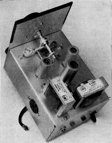
Rear view of the tuner. Note that a double-bearing capacitor is used for tuning the detector circuit. The ceramic padder to the left is C2. The detector is the left of the two smaller tubes. Asymmetrical arrangement of the two audio chokes is for minimum hum pickup.
Building the tuner
Parts arrangement in the tuner is not fussy, but a layout template is available for drilling the chassis if you want it.(1) This is most useful if you use components mechanically similar to those in the original, a restriction that is not too important otherwise. Probably the only critical item is the main tuning capacitor, C1. A double-bearing model with mounting feet front and rear is desirable here, for there may be a slight amount of backlash in the tuning with single-bearing types. A template that comes with the National dial can be used in laying out the front panel. The three potentiometers can be arranged in any convenient manner.
The power and audio circuits were wired with Belden Type 8885 shielded wire. This is not absolutely necessary, but it is a great aid in doing a neat job. Shielded leads can be any necessary length, and can be run in corners of the chassis or wherever convenience dictates, so long as their shields are bonded together at intervals with solder and held in place with an occasional grounding lug. But don't use shielded wire for any circuits carrying r.f.!
Use of insulated tie-point strips for mounting small parts also makes for a neat wiring job. When you assemble the tuner put these strips adjacent to each socket. Use whatever lugs you need and clip off unused ones when the wiring job is done. Cultivate the shielded-wire and terminal-strip habits and you'll have a big jump in the matter of neatness in your construction projects. The AIM Hrtadboot chapter on construction practice will give you other helpful ideas.
Looking at the tuner from the top rear you see the tuning capacitor, C1, and its padder, C2, at the front. The ceramic padder is at the left, with its rotor lug clamped under a washer and its stator lug soldered to the from stator bar of C1. At the right of C1 is the tuning screw for the i.f. amplifier coil, L1-L2. A feedthrough bushing (National TPB) is mounted directly in back of the left-side stator lug of C1. The 10 pF fixed padder, the 50 pF grid capacitor, and the top end of L4 are connected to the underside of this feedthrough.
The detector tube, V2, is at the left, and the i.f. amplifier, 171, is at the right, just in back of C1. The dual audio amplifier, V3, is near the middle of the chassis. The two chokes at the rear and left side of the chassis are L5 and L6, respectively. These are used instead of audio transformers, and just about any small filter choke will serve. Audio transformers are also OK, though somewhat more expensive. The output coupling arrangement, L6, the .05-µf. capacitor, and phone and speaker jacks, are for use with ordinary headphones or a speaker that has its own output transformer (a transformer for use with ordinary audio output tubes will do). A connection directly to the voice coil (low impedance) will not work with this coupling. With speaker leads plugged into the tip jacks, Jl and J2, the speaker is connected automatically when the phones are removed from .13. The position of the jacks and the hole for bringing out the coaxial input lead, on the back wall of the chassis, is not critical.
The male power plug, J4, on the left side of the tinier when viewed from the front, fits into a matching socket on the right side of the modulator unit. To use the tuner at some distance from the modulator, a cable of the required length may be made with an Amphenol 78-S8 socket at the tuner end and an 86-CP8 plug at the modulator end. These should he covered with Amphenol 3-13 plug caps. Placement of the plugs and sockets in the side walls of the various components of the station is not important, so long as they all will match up.
Except for the i.f. and detector coils, L2 and L4, placement of other parts is not critical, and considerable variation from the original can no doubt be made without affecting results. The i.f. coil is a standard Miller slug-tuned unit of approximately 7-µh. inductance. The primary coil, L1, is wound over the bottom turns of L2. It is wound on, cemented in place, and left to dry while other work is done. The turns are in the same direction as the secondary, and the bottom ends of both windings are connected to ground. The top end of L1 is brought to a tie point, where the coaxial line is connected to it.
Bottom view of the tuner. Arrangement of parts, other than the i.f. amplifier coil, L2 (upper left) and the detector coil, L4 (upper right), is not particularly critical. Power and audio circuits are wired with shielded wire.
The detector coils, L3 and L4, are made from a single piece of B & W Miniductor. Start with a piece having at least 20 turns. This fine-pitch coil stock can be cut readily if a sharp knife is held against the plastic supporting strips and heated with a soldering iron pressed against the top edge of the knife. When the blade nears the melting point of the plastic, the ribs can be cut easily. At the sixth turn press the wire down toward the axis of the coil. It may then be cut or broken. Thread the ends back out and unwind a half turn each side of the cut. Now unwind the outside turns until there is left a coil of 4 turns and one of 10%. The tap is made by pushing down the third turn up from the inner end of the larger winding. This makes a point that can be soldered to for the lead to the cathode of the 6CB6.
This assembly is mounted in a horizontal position supported on tie points by its leads, as shown at the upper right in the bottom-view photograph. The outer end of the larger coil goes to the feed-through bushing, the outer end of the smaller to the plate of V1. The balance of the assembling and wiring is almost completely uncritical, though neatness and ease of adjustment will be served if leads are kept short, particularly in the circuits of the amplifier and detector tubes.
Adjustment and operation
If the tuner has been wired correctly it should be possible to hear signals of some sort on it almost at once. Apply 6.3 volt a.c. for the heaters between Pins 4 and 8 of J4. Temporarily connect Pins 2 and 6 together and apply plate voltage, preferably not much over 150 volt at first, positive to Pins 2 and 6 negative to Pin 4. Plug in the phones or speaker. Have all three potentiometers turned down. First try the audio gain control, R3. Turning it up should bring up the level of noise, and possibly hum. Set it at a comfortable level, and turn the i.f. gain, R1, about three-fourths on. Turn up the regeneration control, R2, until a rushing sound is heard. Attach a few feet of wire to the tip of the plug, P1 and turn the dial slowly.
Some signals should be heard, unless you have hit one of those rare times when the 14 Mc range is completely dead. When you find a signal, experiment with the setting of the i.f. gain control, R1, and the regeneration control, R2. If you have never used a regenerative or superregenerative detector before, the intricacies of adjusting it properly will take some learning. Practice with various signals, trying the three conditions mentioned earlier. You may be surprised to find that a little receiver like this can pick up a lot of stuff, once you learn how to tune it properly.
Now, you're ready to peak things up, and get the dial calibration around to what you want. The tuning capacitor, C1, has the ceramic capacitor, C2, connected across it, so the setting of the latter will markedly affect the tuning range of your vernier dial. If you have made your coil correctly, setting C2 to near maximum capacitance will place the 14 Mc amateur band near the maximum-capacitance end of the tuning range of C1. If you succeed in locating the amateur band you will find c.w. signals at the low frequency edge, and phone signals above them. Adjust C2 gradually until the lowest-frequency amateur c.w. signal comes in with the dial close to its maximum-capacitance setting. A good signal to look for now is WWV or WWVH on 15 Mc. One or the other of those stations, perhaps both, will be receivable at least part of the time almost anywhere in the United States. With these and the low end of the amateur 14 Mc band, you have the first megacycle of your tuning range well marked.
Note that an indicating pointer for the dial is made by sticking a triangular-shaped piece of black plastic tape to the nickel-plated rim. Put the capacitor at the maximum setting, and then attach the pointer to the rim so that it is bisected by the left side of an imaginary horizontal line drawn through the center of the dial. When you turn the dial around to bring the capacitor plates all out, the mark will be at the right side. If you have used components similar to the original, you can set the padder, C2, so that 14 Mc is just above the horizontal point at the left, and 15 Mc will come just a bit to the left of vertical. The next megacycle of tuning, to 16 Mc, will occupy slightly less space, and the third and fourth megacycles (to 17 and 18 Mc.) progressively less. This is a fortunate result of the plate shape in the tuning capacitor: the more active lower halves of the v.h.f. bands you will eventually be tuning will be spread out more than the less-occupied frequencies at the high ends.
When you get your converters working, 14 Mc will be 50 or 144 Mc, 15 Mc will be 51 or 145 and so on. The tuner will operate almost exactly the same when working with the converters as it now does on 14 to 18 Mc, except for variations that will be discussed when the time comes. For the moment, you can tune 14 to 18 Mc, and there is a lot going on in that range most of the time. It won't do any harm to practice tuning with this little gimmick, for one of the prices of performance with simple equipment is some trickiness in operation. There is more to running this one than turning the dial!
With the tuner plugged directly into the power supply you may find that the hum level is too high to suit you. This is the result of inductive pickup from the power-supply components by the chokes in the tuner audio circuits. The position of the chokes was adjusted for minimum hum pickup, but it is still considerable at high audio levels. Running the tuner with even a short cable between it and the power supply will bring down the hum level markedly. Use of completely shielded chokes or audio transformers also reduces the hum level, but at higher cost.
Notes
- Templates for use in drilling the surface of the tuner chassis, the top plates of the two transmitter r.f. units and the top surfaces of the two converters are available without charge from the ARRL Technical Department. Be sure to mention the ARRL publication, the edition, the page number, and the equipment for which the template is desired, and send a stamped self-addressed envelope with your request.
Edward P. Tilton, W1HDQ.