The 50 Ohmer transmatch(1)
Getting a 50 Ohm load for your S.S.B. rig.
These days, nearly all manufacturers of single-sideband exciters are building their transmitters with pi-network tank circuits designed to work into a 50 ohm load. If the actual load on such a transmitter is something other than 50 ohm, the amplifier cannot be loaded properly and the over-all operation is not optimum.
Amateurs using such equipment often have multiband beams or trap dipoles which, when fed with 50 ohm coaxial cable, are supposed to present a 50 ohm load to the amplifier. Unfortunately, no antenna designed to cover an amateur band will look like a pure resistance of 50 ohm across the entire band or even a portion of the band. There is bound to be a mismatch as you move across the band. The degree of mismatch depends on many factors. Height of the antenna above ground, its proximity to nearby objects, and its actual impedance at resonance all have an effect on the match between the line and the antenna. The match between the feed line and antenna determines what the transmitter "sees." When the line and antenna are not matched the transmitter won't be working into a 50 ohm load. The basic point to keep in mind is that if the amplifier is designed to work only into a 50 ohm load, any significant departure from this load probably means the amplifier won't do the job it was designed for.
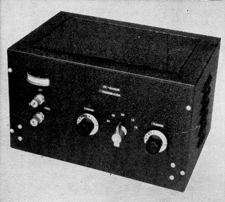
The completed 50 Ohmer is installed in this block crackle cabinet. On the left is M1 and just below it are the controls for S1 and R2. The tuning control near the center of the panel is for C1, the band switch is to the right of C1 and the control for C2 at the far right.
The problem of using coax-fed multiband antennas, and still have the system "look" like 50 ohm load, is not at all difficult. What is required to do the job are two pieces of equipment. First of all, a matching indicator is needed. By matching indicator we mean a device that will show you when the transmitter is actually looking into a 50 ohm load. The Monimatch, or for that matter, any 50 ohm reflectometer, can be installed in the feed line to show when the line is matched. When the line is matched, the transmitter will see a 50 ohm load. However, the reflectometer only shows us what the match is, so the other item required is a device that will make sure the rig is working into a 50 ohm load. What is needed here is an adjustable r.f. transformer. In brief, the transformer can be put in the coax line between the rig and the antenna and adjusted so that the transmitter sees only a 50 ohm load. This is what the 50 Ohmer will do.
What it is
The 50-Ohmer combines a reflectometer and a band-switching adjustable r.f. transformer in one cabinet. It is capable of handling mismatches of about 5 to 1, which is considerably more than you should encounter with any of the coax-fed multiband antenna systems. Fig. 1 is the circuit of the two units. The transformer circuit consists of C1, L1, L2, and C2. S2 is the band switch and is used to short out unused portions of L1 and L2.
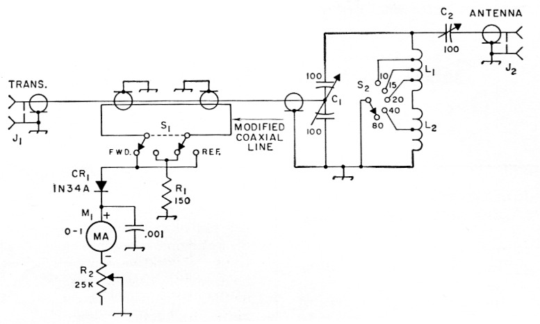
Fig. 1. Circuit diagram of the 50 Ohmer. Decimal values of capacitances are in µF, others are in pF.
| C1 | 100 pF per section, split stator (Hammarlund H FBD-100-C). |
| C2 | 100 pF variable (Hammarlund MC-100-SX or Johnson 100 FD 20H). |
| CR1 | 1 N34A germanium diode. |
| J1,J2 | Coax chassis terminal, SO-239. |
| L1 | 9¾ turns No. 14, 1¾ inch diam., 4 turns per inch (B & W Miniductor 3021, Illumitronic Air Dux 1404T). 14 Mc tap 2½ turns from junction of L1L2; 21 Mc tap 7½ turns from junction of L1L2; 28 Mc tap 7½ turns from junction of L1L2. |
| L2 | 28 turns No. 14, 1¾ inch diam., 8 turns per inch (B & W Miniductor 3022, Illumitronic Air Dux 1408T). 7 Mc tap 5 turns from the junction of L1L2. |
| M1 | 0-1 milliammeter. |
| R1 | 150 ohm, ½ watt. |
| R2 | 25 kΩ control, linear taper. |
| S1 | 2-pole, 2 position switch (Centralab 1462). |
| S2 | Ceramic rotary, one section, one pole, 5 positions (Centralab type 2501). |
A modified length of RG-58/U is used in the reflectometer or bridge. An 8 inch length of wire is installed between the inner and outer conductors of the coaxial line. This pickup wire is terminated in R1, through S1. Power traveling along the line induces a voltage in the pickup wire. In one direction, this voltage will be canceled out in the crystal-rectifier r.f. voltmeter circuit consisting of CR1, M1 and R2. However, power traveling in the opposite direction will cause the voltmeter to read. The bridge is designed to match the impedance of the line, 50 ohm, so whenever a mismatch occurs on the line the voltmeter will show an indication. By using the bridge as an indicator, C1 and C2 can be adjusted so that any reasonable range of impedance values appearing at J2 can be transformed, through the matching circuit, so that at the input end, J1, the transmitter will see a 50 ohm load.
Building the unit
The complete 50 Ohmer is mounted on a 2 × 7 × 11 inch aluminum chassis and installed in a 7 × 12 × 8-inch cabinet (Bud G994). If you already have an s.w.r. bridge, as many of the s.s.b. gang do, the bridge portion can be eliminated and a smaller chassis and cabinet used.
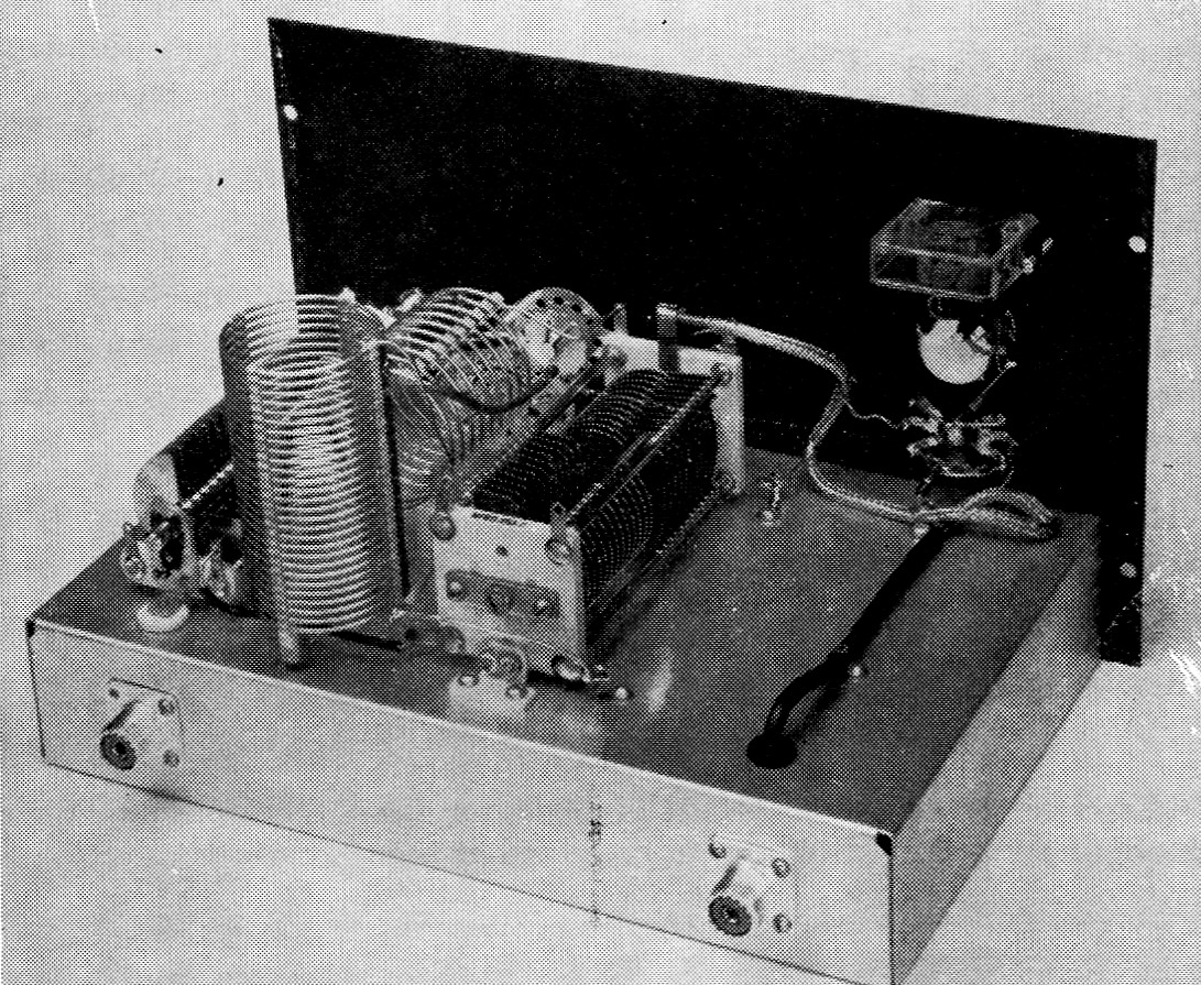
On the right in this view are the components for the reflectometer. The split-stator capacitor is Cs. The vertically mounted toil is Lx, while Li is horizontal C2 is at the left. The chassis fitting on the rear, just below C2, is the output terminal; the other, at the right, is J1.
In the unit shown in the photographs, a 20 inch length of RG-58/U was used to connect from J1 to C1. The pickup wire for the bridge is an 8 inch length of No. 28 insulated wire. Either enameled or cotton-covered wire can be used. Before making up the modified line, install Si, Ml, and R2 on the panel of the cabinet. After S1 is mounted, lay out the coax line as shown in the top-view photograph and mark the coax braid at the two points (about 6 inches apart) near the arms of SI. To insert the pickup wire under the braid, first bunch the braid by pushing it from the end toward the center. Punch a small hole at each point on the braid where it was previously marked. You can then feed the pickup wire through one hole and out the other, leaving about one inch projecting at each hole after the braid is smoothed out. Make sure the pickup wire isn't shorting to the braid, by checking with an ohmmeter. You can then mount the assembly in place, using bent-over soldering lugs to hold the coax line in place on the chassis.(2)
L1 and L2 are mounted between C1 and C2. The low-frequency coil, L2, for 80 and 40, is mounted vertically near the rear of the chassis. The high-frequency coil, for 20, 15, and 10, is mounted horizontally and is held in place by a standoff insulator. A soldering lug is installed on the top of the standoff, the lug being bent around one of the coil turns and soldered. C2 must be insulated from the chassis and panel. Steatite bushings (National XS-6) are used to mount the capacitor on the chassis. An insulated shaft coupler is used to couple the rotor to the tuning knob on the front panel.
Adjustment
The capacitors and coil will handle at least 150 watts, which is adequate for all the commercial s.s.b. exciters. The unit should be installed close to the transmitter, using a short length of 50-ohm coaxial cable to connect the two together. Turn on the transmitter and feed enough power through to obtain a full-scale reading on the bridge. You'll probably have to adjust R2 to get the full-scale reading in the forward direction. Next, switch 81 to read reflected voltage and adjust C1 and C2 for a null, or zero reading on M1. Once you have the zero reading on reflected vs. full-scale forward, the controls should not be changed because the unit is now correctly adjusted and the transmitter is working into a 50 ohm load. Bring up the transmitter power to whatever the manufacturer suggests and you are all set to operate. If you shift frquency, it is a good idea to check the match to see how much it has changed. You will probably have to touch up C1 and C2, depending how far you QSY. Keep a record of the settings of C1 and C2 for each band and you'll find it will only take a few seconds to rematch after changing bands.
Notes
- A generic name coined by the editors to apply to any type of matching network inserted between a transmitter and a transmission line. There has been an obvious need for such a term, since "antenna coupler" is inadequate both technically and psychologically.
- For additional information on this type of reflectometer, see Bunee, "The 'Mickey match'," QST, November, 1958, and the chapter on measurements in The Radio Amateur's Handbook.
Lewis G. McCoy, W1ICP.