Semiconductor rectifiers
The characteristics, and how to use them.
The semiconductor power rectifier is gradually losing that "expensive" tag, and the cheaper it gets the more attractive it becomes in transmitting power supplies. But some hams have learned, to their sorrow, that you can't take the liberties with crystal diodes that you can with many tube rectifiers. Here's why - and how to avoid trouble.
Semiconductor rectifiers are becoming popular in amateur equipment, both in the home and in the car. While this type of component has a justifiable reputation for reliability, in actual application the semiconductors have certain weaknesses that must be considered before their inherent reliability can be attained. This article briefly discusses some of the characteristics of the rectifiers and lists some precautions helpful in their use. Discussion is limited to the germanium and silcon types.
How a rectifier works
A rectifier is a component that conducts electricity better in one direction than the other. Any electrical part that meets this requirement can be used as a rectifier. Many varieties of rectifiers are or have been used. Old timers may remember the electrolytic rectifiers and detectors that were used on occasion between 1900 and 1930, in which metals and chemical solutions were combined in forms very similar to present-day electrolytic capacitors. Mechanical rectifiers have been used when the characteristic of the input electrical wave was known (like ordinary a.c.) and switches were closed only when the current was flowing in a particular direction. The car radio synchronous vibrator used in the era before transistor radios was an excellent example of this type. However, vacuum-tube and mercury-vapor rectifiers have almost entirely replaced the mechanical and electrolytic types because, having electron-triggered or electron-flow methods of conduction across the open space in the tube, these rectifiers only conduct with one polarity of applied voltage.
Like the electron tube, the semiconductor rectifier also operates on the principle of electron attractions. A crystal is formed of silicon or germanium (Fig. 1) with impurities added in one region differing from those in the adjacent regions. The result of these impurities is that one part of the crystal structure has more electrons than the structure calls for, while the other region has too few. The vacant parts of the structure of the second region are called "holes." The electrons are negative charges of electricity, and the holes are positive charges. (Where a material has neither holes nor electrons that can be easily moved by applied voltage, the material is an insulator.) The region of extra electrons is,called the n region, that with extra holes is the p region.
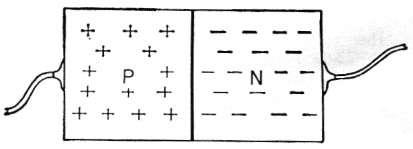
Fig. 1. Rectifying semiconductor junction with excess electrons (n region) and electron vacancies or "holes" (p region).
The boundary between the regions, or p-n junction, is where the rectification takes place. If the p region is connected to the positive terminal of a battery while the n region is connected to the negative terminal, the charges will cross the junction and be replaced by charges from the battery. If the battery is reversed, the charges will tend to be drawn away from the junction by the battery, and there will be no free charges in the immediate vicinity of the junction to carry current across it. This makes the junction look like an open circuit when "reverse" polarity is applied to the rectifier, and automatic rectification takes place with voltage polarity change.
Power loss
The semiconductor rectifier is not perfect. The differences in material on opposing sides of the p-n junction make it slightly difficult for current to cross the junction when only a small forward voltage is applied. Germanium usually requires about a fifth to a half volt in the forward direction before full current will flow, while silicon requires six-tenths of a volt to a volt for each junction. This voltage drop required to cause current flow means that power is lost in the junction (watts = volts X amperes) and some heat will develop. The semiconductor rectifier is attractive because the voltage and power loss are less than in many other kinds of rectifiers.
Semiconductor rectifiers are not perfect in the reverse direction, either. Fig. 1 shows the electrons and holes as if their regions were exclusive, but there are always a few holes in the electron region, and a few electrons in the hole region.
A semiconductor region is mostly p or mostly n, in the same sense that a town may be Democrat or Republican. The effect is that of the majority. Also, small breaks in the crystal structure make current carriers available. These carriers, if located near the p-n junction, will cross it when reverse polarity voltage is applied and permit reverse current flow. In spite of this, modern semiconductor rectifiers that are rated for one ampere commonly have less than a milliampere reverse current at room temperature. High reverse voltage multiplied by leakage current also represents power loss that appears as rectifier heating.
Temperature has a very important effect on leakage current, for as the material of the semiconductor warms, the unwanted carriers become more active, and more of them will contribute to leakage current. A common rule-of-thumb is that the leakage current will double with each 18 degree Fahrenheit rise in temperature. This effect is reversible; that is, as the temperature drops, the leakage current will drop to almost its original value unless the rectifier has been damaged. Too much heat will destroy the rectifier. The heat may come from either internal power dissipation or from outside. It is best to keep germanium below 200 degrees F. and silicon below 300 degrees F for long life.
Circuits and their effect
Three types of rectifier circuits, Fig. 2, may be expected to be found in amateur equipment. Table I lists a number of conditions that the circuits impose on the rectifiers. The chart expresses the voltages, currents, and powers in terms of the d.c. output voltage, current, and power. Thus, where peak inverse voltage is listed as 3.14, the peak inverse (reverse) voltage impressed on the rectifiers when the d.c. output voltage is 1000 volt would be 3140 volt. Naturally, the rectifier in such a circuit should be able to stand this inverse voltage.
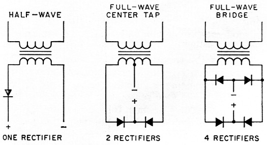
Fig. 2. Several common single-phase rectifier circuits (See Table I). Series strings of rectifiers may be used for increased voltage ratings where single rectifiers are shown.
| Circuit | 1 | 2 | 3 |
|---|---|---|---|
| D.c. volt out | 1.00 | 1.00 | 1.00 |
| Peak volt out | 3.14 | 1.57 | 1.57 |
| Rectifier peak inverse volt | 3.14 | 3.14 | 1.57 |
| D.c. current out | 1.00 | 1.00 | 1.00 |
| D.c. current per rectifier | 1.00 | .500 | .500 |
| R.m.s. current per rectifier (resistive) | 1.57 | .785 | .785 |
| R.m.s. current per rectifier (inductive) | Res. only | .707 | .707 |
| Peak current per rectifier (resistive) | 3.14 | 1.57 | 1.57 |
| Peak current per rectifier (inductive) | Res. only | 1.00 | 1.00 |
Table I deals only with cases where the rectifier (semiconductor or tube) is feeding pure resistance or an inductance above the critical value.(1) When the rectifier is connected directly to a capacitor, the capacitor has a tendency to look like a short circuit during charging, both initially and on every rectifying cycle. Most rectifiers, and particularly semiconductors, have ratings for maximum surge current, both for the initial surge (one cycle or a few cycles) and for repetitive surge - that is, the charging that occurs on the conducting part of each cycle after the filter capacitor is once charged. The source of power, whether transformer or line, should have enough resistance or inductance added to it in series to limit the surge currents to the maximum safe value. With a capacitor-input filter, the peak inverse voltage may range up to two times the peak voltage developed across the filter, depending mainly on how heavily the rectifier output is loaded.
Connecting rectifiers in series for high voltage
The low cost of the lower-voltage silicon rectifiers, in particular, has provoked the thought of series connection for high-voltage operation. This is quite possible, provided the characteristics of the particular pieces are known; the rectifier manufacturers commonly use series connection to make high-voltage stacks.
Rectifiers tend to behave in either of two ways when subjected to high reverse voltage, as shown in Fig. 3. In either of the cases a voltage is finally reached where the voltage within the rectifier forces the material to become conducting. Some rectifiers have practically no conduction until a critical voltage is reached, and then the leakage current increases hundreds of times with a rise of a very few volts. This is typical of small-area silicon junctions. Other rectifiers have a continual and usually more rapid increase in leakage current with increase in reverse voltage, showing a gradual rather than abrupt increase into high reverse current as high reverse voltage is reached - typical of germanium and large-area silicon rectifiers.
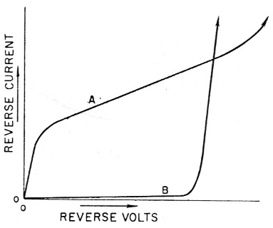
Fig. 3. Rectifier A leakage current increases gradually when reverse voltage is increased, while B exhibits a sharp increase at a particular voltage. A is typical of germanium and large-area silicon units, while B represents many small silicon rectifiers.
In both cases, immediate and disastrous destruction can result unless the current is limited. The ordinary catalog or handbook description gives no clue as to how a particular type of rectifier behaves in this region, and thus applied voltages should never be more than maximum ratings. Occasionally typical curves are shown that illustrate how a manufacturer expects his product to enter the region of rapid increase of reverse current, but it is impossible for a maker to check each inexpensive rectifier for compliance. In cases where only a single rectifier has reverse voltage applied to it, this region is relatively unimportant, because it always lies at a higher voltage than the rating. The region is important when two or more rectifiers are connected in series to obtain a higher total voltage rating.
When two semiconductor rectifiers are connected in series, how does the voltage divide? Let us imagine two rectifiers in series having to divide 800 reverse volts, and having the reverse characteristics shown in Fig. 4. As this is a series circuit, the reverse current must be the same in the two rectifiers, and the total of the voltages developed must add up to 800 volt. The situation here is intentionally bad, with one rectifier having a "sharp" break and the other a "soft" break in the reverse current-voltage curve. Here we see that at 100 microamperes the rectifier with the soft break is subjected to 200 volt and the sharp-break rectifier must withstand 600 volt. This means that the rectifier with 600 volt across it will have to dissipate three times the power of the rectifier that has the higher leakage current in normal service. It will, of course, become hotter, and its own leakage current will increase until a somewhat more equal distribution of voltage occurs. The danger in this compensating process is that destruction may occur before a satisfactory equalization is reached. For this reason manufacturers, when assembling series strings, frequently make certain that the diodes used in each string have the same type of break and, if a soft break, are pretty well matched.
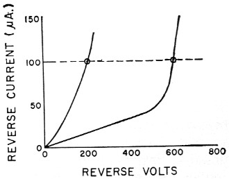
Fig. 4. Division of 800 reverse volt across two series rectifiers having the characteristics shown would result in one rectifier having only 200 volt and the other 600 volt.
General Electric practice(2) is that strings of germanium rectifiers such as the 1N91 should be factory-matched while medium- and high-current silicon units (like the 1N1301) are well-enough matched if they have the same type number and peak inverse voltage rating. With low-current types - for instance, the 1N253, 1N440, 1N536, 1N1115, and 1N1487 - having a sharp knee or break, no particular matching of reverse characteristic or selection of peak inverse voltage rating is required.
When the diodes have a sharp break, the total current is usually low enough to prevent developing enough power to cause destruction if at least a moderate amount of safety factor has been allowed in choosing rectifier voltage ratings. Longer strings of the same type rectifier are inherently safer. Incidentally, it is uncommon to shunt rectifiers with resistors to equalize voltages, though it could be done. One reason not to would be because the voltage division during most of the reverse cycle would differ from the division at transient peak voltages. An example of the difference is shown in Fig. 5, where rectifier B (uncompensated) would have greatest impressed voltage normally, but not during transients.(3)
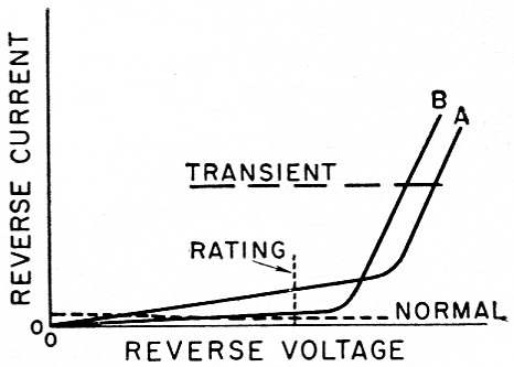
Fig. 5. A pair of rectifiers (A and B above) may make resistive equalization of voltage difficult. At rated voltage, A here has the lower resistance, but B has a lower resistance at the transient condition.
Transients frequently cause different voltages to appear across rectifiers in a series string. Each diode appears as a small capacitor and, of course, each lead of that capacitor has a certain capacitance to ground as in Fig. 6. This string acts as a voltage divider. If we assume that a pulse with a very steep wave front is coming from the left and has reverse polarity, the biggest portion of that pulse is going to appear across the left-hand rectifier. A more equal division of voltages can be achieved by shunting the rectifiers with equal capacitors of 1000 picofarad or more. In long strings it is sufficient to shunt possibly as many as three or four rectifiers at a time (the same number at a time, of course) with satisfactory results. The reason for the unequal distribution of voltage without the compensating capacitors is that the stray ground capacitances (in the example shown) cause current to be bypassed to ground as the transient moves from the left to the right, and little of the transient appears across the right-hand rectifiers.
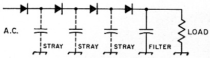
Fig. 6. Transients coming from the a.c. source affect the left-hand rectifiers most because of the bypassing effect of the stray capacitances. Capacitance compensation can help (see text).
Transients should be expected to appear even when the power source feeding the rectifier is stable. Switching on the power at a time when the input a.c. is at the peak of the cycle is one cause; the presence of a transformer with inductance in the switched line is another. One source of transients that is not so obvious is in the rectifier itself. The current carriers in the rectifier are usually in motion across the p-n junction at the time of polarity reversal of the rectifying circuit. These carriers are so close to the junction that they will often recross it and give the effect of reverse current, and it does take an appreciable amount of time for them to be cleaned out. This process makes the rectifier look as if it is shorted for this period and, particularly in the case of bridge rectifiers, when the "shorted" period is over for one rectifier, another rectifier or rectifier string suddenly sees whatever voltage the a.c. source has reached during this period.
Rectifiers in parallel
In the forward direction, a semiconductor rectifier has many of the characteristics of a voltage regulator in that once the threshold voltage (a fraction of a volt) has been reached, the rectifier will conduct very greatly increased current before the voltage rises more than a few additional tenths of a volt. Rectifiers of the same type do not all have exactly the same threshold voltage. If two such rectifiers are paralleled, the difference in the voltage drops will mean that the rectifier having the lower voltage drop will carry the greater current. Equalizing resistors should be used in series with each rectifier, as in Fig. Fig. 7, making the resistance value such that there is a drop of perhaps one volt at the rated current. This makes the difference in voltage drops of the rectifiers have little effect on the even distribution of current.
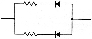
Fig. 7. Small equalizing resistors help divide forward current between paralleled rectifiers (see text).
Insulation and heat sinks
Most rectifiers in the power range have a case that is connected to one of the leads, though there are a number of all-glass types. The "hot" case must be insulated by air spacing or other means from the rest of the circuitry to prevent accidental shorts.
This insulation causes some problems when the rectifier is dissipating an appreciable amount of power, for some means must be provided for removing the heat from the rectifier. Most rectifiers that need this treatment to meet their advertised ratings are equipped with a threaded stud mount. There are available mica washers that may be used to provide electrical insulation while permitting considerable heat transfer to the chassis or other metal body the part is mounted on. There are also power rectifiers available with insulated studs that are useful for mounting directly against the chassis. Here, as with the mica washers, the stray capacitance to ground is increased.
Another way of providing cooling for the rectifier is to mount the stud into a metal plate having an area of several square inches, and permit free air or blown air to cool the metal plate. It is necessary to insulate the plate if the stud is in electrical contact with the rectifier.
Acknowledgment
The writings of many other authors, notably that of F. W. Gutzwiller, were freely consulted in the preparation of this article. Much was recast into the above wording, and errors of interpretation, if any, are this author's.
Notes
- See the "Power supply" chapter of The Radio Amateur's Handbook.
- General Electric Semiconductor Products Department, "Series Operation of Silicon and Germanium Rectifiers." Publication ECG-400 3;59.
- This discussion assumes that transients are infrequent but cannot be avoided.
David T. Geiser, WA2ANU.