The Nikey
An improved keying mechanism for all types of electronic keyers.
Several previous QST articles on the subject of electronic keys have pointed out the advantages of an actuating switch in which independent arms for dot and dash contacts are provided. This article shows a simple and inexpensive way of making such a switch.
With the advent of the new "space-age" speed merchants, and an effort to emulate same, a TO keyer and commercial keying mechanism were purchased. After operating the TO keyer for a while, it was felt that a further improvement in "copy" could be made by constructing the transistorized "Ultimatic" keyer.(1)
As indicated by the article, the full value of this keyer is realized by a mechanical key with separately-articulated levers for dot and dash operation. A requirement at this station was to have this mechanism a separate unit instead of being built into the electronic-keyer package as described in KIMHU's article.
The key, as described herein, was checked out with the TO keyer and a surprising improvement was immediately noticeable. The reason for this improvement becomes apparent when it is realized that a great deal of lost motion (moving from the dot contact to the dash contact) is eliminated because of the articulated levers.
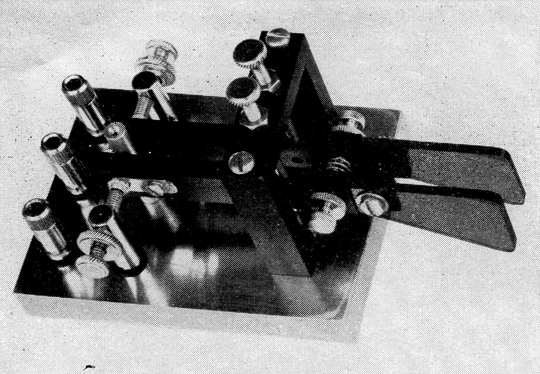
The Nikey-a control switch with separately-articulated dot and dash levers for use with electronic keyers. Each movable contact is riveted to a small strip of copper fastened to the lever with a 6-32 screw. The screw hole in the strip is slotted to permit alignment.
Base
Referring to the photograph, it can be seen that all parts were available from a discarded bug key, a hardware store handling Reynold's aluminum bar stock, and the storehouse of a ham's ingenuity. The first requirement for the key was a base of sufficient weight to hold the key firmly to the operating desk. The 3 × 4 inch base, ½ inch thick, of cold-rolled steel, was obtained from a local model shop. Lighter material may be substituted if some provision is made to prevent the key from sliding on the operating desk. The binding posts were available from the junk box. The dot and dash contacts are isolated from the base with insulating shoulder washers.
Keying levers
The bridge and keying levers are made from ¼ × ½ inch aluminum bar stock. Other material, such as brass or cold-rolled steel, would be satisfactory. The bridge and levers are drilled and tapped as indicated in Fig. 1. Fixed contacts, which are attached to the keying levers, are from an unused relay, and are attached as indicated in the photograph. Note the clearance holes in lever immediately behind the contacts. These holes allow clearance for a riveted-type contact.
Pivot rods
The pivot rods are constructed of 3'-inch stainless-steel rod, but either brass or cold-rolled steel would be suitable substitutes. The pivot rods are retained in the levers by means of 5-inch 6-32 set screws which may be removed from discarded knobs. The pivot rods are machined to a cone shape by inserting the rod in a drill press, or electric drill, and using a fine file to shape the rod to the desired point. The bridge pivot screws (with holes) were obtained from the discarded bug key. The base pivot screws are M-inch 6-32 cup-point Allen set screws. This type of set screw may be also used for the bridge pivot screws in place of the screws indicated. The pivot rods should be radiused or rounded for use with cup-pointed set screws as opposed to a definite point for use with pivot screws with holes (as used on the bridge).
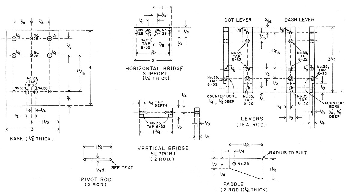
Fig. 1. Sketch showing details and dimensions of components required for the Nikey.
Spring
Spring tension is supplied by the use of the dot-return spring from the discarded bug. By locating the return spring between levers, as shown in the photograph, only one spring is required. Adjustment of spring pressure requires the use of only one adjusting screw. This adjusting screw and lock nut were obtained from a 69-cent straight key. The other adjusting screw appearing in the photograph was added only as "dress," to provide a balanced appearance.
The paddles were cut from 1/8 inch Lucite but may be of 1/8 inch phenolic or other material on hand that can be shaped to individual preference. The rear stop post is a ¼ inch spacer, 1½ inches long, tapped, 6-32. Three rubber feet are fastened through the base to the vertical bridge supports and rear stop post.
Adjustment
The procedure in adjusting the key is to first position and center the lever contacts on the stationary contacts by adjusting the height of the pivot screws. The bottom pivot screws are locked in position. Final adjustment is made by tightening the top pivot screws until the vertical and horizontal motion of the pivot rods is eliminated and then loosening these screws slightly until there is no restriction in the radial motion of the levers.
To utilize this key to its fullest advantage, the contacts should be as close together as possible without making contact. This spacing will be in the order of 0.002 to 0.004 inch.
To provide a finished appearance, the base was cadmium-plated with an iridescent coating. The bridge and levers were anodized black. After anodizing, all tapped holes in the levers were retapped to clean the threads for good electrical contact.
When the key is properly adjusted, you will notice a decided improvement in your keying. With a little practice on the Nikey, one should be able to acquire the necessary orbital speeds to join the "spacemen" at the low end of 7 Mc. This key should prove versatile for use on the Ultimatic, TO, and all other forms of electronic keyers, and for the real old-timer who may get nostalgic and use it as a side-swiper.
Notes
Nicholas Lefor, W2BIQ.