An introduction to the klystron
Up to a year or so ago, few amateurs even considered making use of frequencies higher than 450 Mc, and those who did went at it with line-of-sight paths and low power as the modus operandi. Now, with moon bounce and satellite reflection established facts, and space communication just around the corner, we are on the threshold of an era that should see great amateur interest in u.h.f. and microwave techniques. One of the tools we may soon be using is the modern power klystron. Here is an opportunity to learn something of how these marvelous devices work, to prepare for the big push to frequencies above 1000 Mc that almost certainly is in the offing.
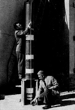
Klystrons come in all sizes, capable of handling anything from milliwatts to megawatts, at frequencies from about 200 Mc up. Here W6UF and W6CHE show the giant size of an Eimac X-26 three-cavity klystron. Almost 10 feet high, this ceramic-insulated stovepipe is capable of better than 1.25 megawatt pulsed output in the 400 to 450 Mc range.
As each successively higher-frequency amateur band becomes popular, new techniques must be employed to fully exploit its DX capabilities. U.h.f. communication by way of the moon and reflecting or relaying satellites holds promise of being one of the more exciting facets of amateur radio of the near future. The 1215 Mc band is well suited for these modes of radio communication because high-gain antennas are of reasonable size, and receivers can be built with low noise figures. In this frequency region the power klystron is the tube of the future.
A high-power final amplifier for the 1215 Mc band requires techniques and components new to the amateur art. Over the past ten years the power klystron has become the most widely used amplifying device for power levels of one kilowatt or greater at frequencies above 300 or 400 Mc. As the state of the communication art progressed over the years, it became apparent that conventional v.h.f. tube types suffered from limits of frequency and power handling capability. Transit time is the major fundamental reason that equipment designers are forced away from traditional tubes to the newer microwave tube types, of which the klystron has found widest use in high-power amplifier service.
Transit time is a phrase used to describe the finite time of flight of an electron between electrodes in a vacuum tube. When the electron transit time from cathode to grid and from grid to anode becomes an appreciable part of the r.f. cycle, efficiency, gain and general performance of the tube are severely reduced. Some excellent work has been done by tube designers through the years to reduce transit time in conventional tubes by making the spacing between elements very small. Unfortunately, this results in tube designs which are difficult to fabricate and which have severe power handling limitations. For a kilowatt at 1296 Mc., "something new must be added!"
Velocity modulation
In the conventional r.f. power tube, the electron flow from cathode to anode is chopped into short pulses of current each r.f. cycle by the grid. The charging of the output tuned circuit by these pulses (or bunches) as they reach the anode produces r.f. power output. At low frequencies, the pulses can be of controlled duration and well defined. At ultra-high frequencies, transit time effects cause the bunches to be poorly defined, degrading tube performance.
In the power klystron, well-defined electron bunches are formed from a continuous electron beam, by a technique called velocity modulation. The klystron uses transit time to advantage in producing reasonable efficiency, exceedingly high gain, and other desirable characteristics such as constant input power regardless of signal, good linearity, and high stability.
How the amplifier klystron works
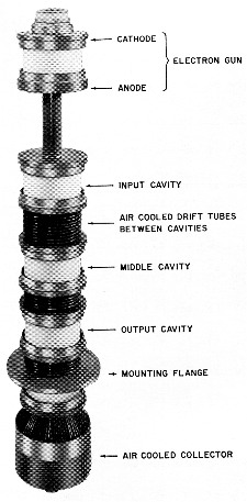
Referring to Fig. 1, the essential parts of the amplifier klystron are the electron gun, the drift tube, the resonant cavities, and the collector. The electron gun consists of a cathode, an anode and a focusing electrode, which act to form an electron beam. Electrons from the heated cathode are accelerated and attracted toward the anode and, therefore, a current flows as in a diode, when high-voltage d.c. is applied to the anode.
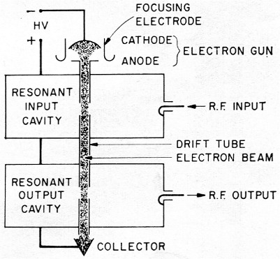
Fig. 1. Simple two-cavity klystron illustrates theory of "bunching." The electron beam passes from cathode to collector via the drift tube and is influenced by action of resonant input cavity, which acts to bunch electrons into groups. Energy is extracted from the electron beam to excite the output cavity and provide r.f. output.
The gun electrodes are arranged to focus the accelerated electrons through a hole in the center of the anode. The electrons form into a cylindrical electron beam which flows at constant velocity through the resonant cavities and hollow drift tube into the collector. R.f. drive power applied to the coupling loop on the input resonant cavity causes r.f. voltage to exist between the re-entrant cavity posts. (See Fig. 2, evolution of the resonant cavity from a lumped tuned circuit.) These posts are also the ends of adjacent drift tube sections. The spaces between adjacent drift tube ends are called interaction gaps. Interaction between the cavity r.f. voltage fields and the electron beam takes place in these gaps. Electrons flowing past the input gap are affected by the r.f. exciting voltage existing across the gap. During the instant when the r.f. voltage is "positive" (in direction of electron flow), electrons in the gap are very slightly accelerated. An instant later, during the alternate half cycle of r.f. voltage, the cavity field has reversed and electrons in the gap are retarded. Some of the electrons flowing in the beam are now moving faster and others are moving slower than the average rate. The beam is velocity modulated. As the beam drifts toward the resonant output cavity, the fast electrons tend to catch up with the slower electrons, in a process called bunching. When the electron bunches reach the output cavity gap, they are well formed, and charge the output resonant circuit, acting as sharp pulses of r.f. current. The cavity acts as a resonant coupling device, and power is coupled from the cavity to the transmission line and antenna.
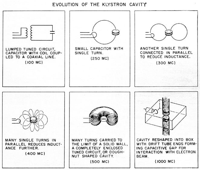
Fig. 2. The klystron cavity may be thought of as evolving from a simple resonant circuit. A small capacitor with a single turn loop (center, top drawing) is revolved through 360 degrees to produce a three-dimension resonant cavity. The cavity walls provide the circuit inductance, and the center portion provides the capacitance (center, lower drawing). A slight physical modification of this concept results in the square resonant klystron chamber. The ends of the drift tubes provide the resonating capacitance, and the box may be tuned by varying the volume by means of movable walls.
A comparison may be drawn between the interaction of electron bunches with the output cavity and the interaction of r.f. pulses between screen and anode in a conventional tetrode operating at low frequencies. The essential difference is that in the klystron, the electron bunches are not formed by a control grid, but rather by velocity modulation of a continuous electron beam.
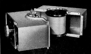
There is more to a typical klystron amplifier than is shown in the simplified diagrams of Figs. 1 and 2. The 3K2500LX three-cavity klystron used in the recent moon-bounce experiments(1) is shown in the photograph on page 15. Fig. 3 shows this tube mounted in an Eimac Amplifier Circuit Assembly. The socket provides connection to the heater, focus electrode and cathode. The magnet frame assembly provides support for the klystron and magnet coils. It is made of iron and provides a return path for the axial magnetic field and serves to shield the magnetic field from components outside the magnet frame. The magnetic field keeps the beam focused as it passes from the gun, through drift tubes and cavities, to the collector. The prefocus coil, mounted in an iron frame atop the assembly, provides a magnetic lens for focusing the beam into the main magnetic field.
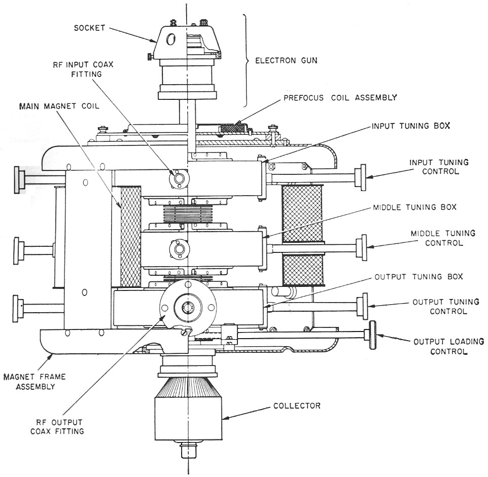
Fig. 3. Cutaway section of three-cavity klystron. The klystron is mounted in a magnet assembly which supports the tube, tuning boxes and magnet coils. Prefocus coil is mounted atop the frame. Cavity tuning is accomplished by the three tuning controls at right and left. Klystron is cooled by air blast directed at cooling fins mounted along the drift tube.
Most power klystrons have three or more cavities, because a multiple-cavity klystron will provide substantially higher gain and efficiency than the simple two-cavity tube. Klystrons have been built with six or more cavities, having power-gain figures in excess of 90 db. On the next page is a detailed view of an Eimac external cavity, showing how it is fastened to the klystron to complete the r.f. circuit. The knob at the left serves to move tuning doors, changing the volume of the box and hence the resonant frequency. A typical input coupling loop (top center) and metallic finger stock for good r.f. contact may be seen in this view. For the moon-bounce amplifier, these tuning boxes were modified in size with file, hacksaw and solder to tune to 1296 Mc. Tuning controls to adjust the resonant frequency of the input, middle, and output cavities of the klystron are shown in Fig. 3. The output loading control adjusts the load coupler which is used to change the position of the antenna coupling loop in the output cavity.
Amateur use
Setting up a complete 1215 Mc final amplifier around a klystron and associated hardware is largely a matter of doing a good mechanical job and applying the proper a.c. and d.c. voltages. You don't have to be a genius to do it right. Fig. 4 is a simplified diagram showing the important power connections and defining the various symbols commonly used with these klystrons.
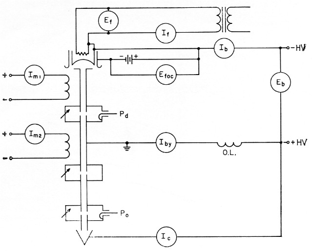
Fig. 4. Simplified schematic of d.c. klystron circuits. Note that positive potential of collector supply is at ground potential. The following terms are used to indicate klystron potentials and currents:
Ef-filament voltage; If-filament current; Eb-beam voltage; Ib-beam current; Iby body current; Ic-collector current; O.L.overload relay coil; Im-magnet current; Pd-driving power; Po-output power.
In addition to the electrical characteristics listed in Fig. 4, the following formulas will be found to be useful:
Efficiency, per cent = Po / (Eb × Ib)
Beam transmission, per cent = (Ib - Iby) / IbFilament voltage is obtained from a transformer which must be insulated for more than the beam voltage as the filament assembly of the klystron is at a high negative potential with respect to ground. Filament voltage should be metered at the tube terminals. The beam current (Ib) meter reads all of the current leaving the cathode of the klystron. Most of this current arrives at the collector (le). The remaining current is lost to the klystron body during the long trip from cathode to collector. Current lost to the anode and drift tubes is called body current (Iby). This loss current should be held to a very small value so that the beam transmission efficiency is higher than 90 per cent and the body current overload relay (O.L.) should be set accordingly. A collector current meter is unnecessary since le = Ib - Iby.
The Eimac 3K250OLX is an example of a three-cavity klystron. The tube is forced-air cooled, and uses ceramic insulation. The tuned chambers are external to the tube, in the form of resonant boxes placed around the cavities. The tube is usually mounted in a vertical position, with the electron gun at the top of the assembly.
The focus electrode draws very little current (about 5 mA, max.) so the voltage may be obtained from a small power supply, battery, or cathode bias resistor well insulated from ground. The d.c. potential for the magnet coils should be adjustable and must be metered. You can tell if the klystron has sufficient r.f. drive power by the way it tunes, so a drive-power indicator is unnecessary. A calibrated power-output meter is a nice convenience, though expensive. Some indication of relative output is essential for proper tuning. An adjustable probe or loop connected to a crystal diode and meter (Po) and arranged to sample the output coaxial line is all that is necessary.
The body-current and relative-power-output meters are important during tuning and should be physically located so that they may be conveniently viewed while adjusting the klystron.
Model of external klystron cavity. The tuned chambers clamp about the ceramic sections of the tube shown in the picture on the next page. Tuning adjustments are made by moving the adjustable end sections of the chamber. The ceramic section of a typical klystron is shown ready to be affixed within the cavity.
Typical operating characteristics of the 3K2500LX in amateur service are as follows:
Ef 7.5 V a.c.
If 5.8 A a.c.
Eb 4.5 kV d.c.
Ib 220 mA
Efoe 90 V d.c.
Iby 25 mA
Im1 0.5 A d.c.
Im2 2 A d.c.
Pd 2 W
Fo 1296 Mc
Pi 1000 W
The efficiency of the klystron operating under the above conditions is quite low, about 30 to 35 per cent. The power output therefore is about 300-350 watt.
The 3K2500LX was designed for ground military use at 1 kW power output on a somewhat lower frequency band. For one-kilowatt input amateur service, the klystron must operate at approximately one-half the design voltage, and on other than the design frequency. Had the klystron been designed specifically for the amateur 1215 Mc band, the driving power required would be only a few milliwatt.
Tuning the klystron amplifier is quite simple; possibly easier than an equivalent lower-frequency transmitter using conventional tubes. First, the filament voltage is set to 7.5 volts, and five minutes is allowed for the cathode to reach operating temperature. Now the magnet currents are set at 0.5 A and 2.0 A. Apply about 2 kV beam voltage and adjust the pre-focus coil position and current for minimum body current (about 15 mA). Bring the beam voltage up to operating level (4.5 kV) and again adjust the pre-focus coil for minimum body current. The beam current should now be approximately 220 mA.
Apply excitation and bring the r.f. drive level up to about 100 milliwatts. Increase the coupling of the sampling loop until there is an indication on the output meter. Set the output loading control for maximum (loop position vertical in the cavity). Tune the middle cavity slightly above resonance (adjust so as to reduce the volume of the cavity). Now increase the drive to about two watts and tune the middle cavity back toward resonance for maximum power output. You will know you have sufficient drive if in tuning further toward resonance the power output drops suddenly to about 10 per cent of its maximum value.
Tune the cavity lower in frequency for maximum power, touch up the magnet currents, and you're on the air! Good luck; see you on the high end!
The future
This is just the beginning of one of the most enticing eras for amateur radio. Today, a klystron costs about as much as a good complete s.s.b. station, so don't rush down to the local parts house for your new moon-bounce bottle this week. Few hams could afford the first s.s.b. stations, nor could more than a few buy the first rotary sparks. History will repeat itself, however, and inexpensive parametric amplifiers and velocity-modulated klystrons may grace the shacks of the average hams of the future. In any event, with moon bounce and satellite reflection an accomplished fact, and actual space communication probably not far off, it's certain that future DX men will not be entirely dependent upon the vagaries of the sunspot cycle. Widespread amateur interest in u.h.f. communication is nearer than you think!
Notes
George Badger, W6RXW.