The grounded-grid linear amplifier
Effect of circuit design on linearity and stability.
Timely information on operating the popular grounded-grid circuit to make the most of its inherent advantages as a linear amplifier.
In the "good old days" of ham radio, linear amplifiers were used by a few amateur phone stations as a (relatively) inexpensive way of obtaining high power. Class-B modulators were as yet unknown, and the cost of glassware necessary to generate two or three hundred watts of Class-A audio power was exorbitantly expensive for all but the well-heeled hams.
Loy Barton's classic QST article (circa 1931) describing the inexpensive Class-B modulator system sounded the death knell of the linear amplifier for amateur service until the advent of single sideband, which recently blew the dust from this ancient mode of operation and modernized it to fit today's operating conditions.
What is a linear amplifier?
To the hi-fi enthusiast, the linear amplifier is a high-fidelity music amplifier. To the s.s.b. enthusiast, the linear-amplifier package, when placed on the end of a sideband exciter, will make the exciter sound bigger, louder, and more commanding to other amateurs. The fact of the matter is that the s.s.b. linear amplifier is a high-fidelity amplifier in the true sense of the word. Although the hi-fi man thinks in terms of fidelity, and the sidebander thinks in terms of linearity, they are both talking about the same thing.
It is interesting to note that a good hi-fi audio amplifier can theoretically be converted into a low-distortion linear amplifier for side-band service by replacing the audio circuits with suitable r.f. tank circuits. Indeed, for r.f. work, push-pull circuitry is not even required as it is in audio service, because the flywheel action of the r.f. tank circuits will supply the missing half cycle. Finally, the operating parameters for a particular tube - plate, screen, and grid voltages, driving voltage, load resistance - are easily calculated for audio work, and apply equally well for r.f. service. For example, the 811-A tube is rated for Class-B audio service as a high-n triode. Compare these ratings with the Class-B r.f. linear data listed in Table 1.
Why linearity?
For sideband service the r. f. power amplifier must be truly linear. It must be capable of high-fidelity reproduction. That is, the envelope of the signal existing in the plate circuit must be an exact replica of the envelope of the exciting signal. This statement is a good definition of a linear amplifier. It implies that the power gain of the stage must be constant regardless of the signal level. Any deviation from this happy state creates distortion products that appear in the signal passband and adjacent to it.
| Class-B Audio Service (Two Tubes) | Class-B R.F. Service (S.S.B.) (One Tube) | ||
|---|---|---|---|
| Grid Driven | Grounded Grid | ||
| Plate Voltage | 1250 | 1250 | 1250 |
| Grid Bias | 0 | 0 | 0 |
| Peak Grid Voltage | 175 | 88 | 88 |
| Zero Signal Plate Current (mA.) | 54 | 27 | 27 |
| Max. Signal Plate Current (mA) | 350 | 175 | 175 |
| Load Resistance (ohm) | 9200 | 4600 | 4600 |
| Max. Signal Grid Current (mA)(1) | 26 | 13 | 13 |
| Power Output (watts) | 310(2) | 155(2) | 141(3) |
| (1) Varies from tube to tube. (2) Computed power output. (3) Measured output including circuit losses. | |||
| The operating parameters of a Class-B amplifier stage remain the same regardless of whether the tube functions in audio or r.f. service. Grounded-grid operation is similar, except that the exciter must supply additional feed-through power. Since Class-B audio service requires two tubes, all currents and plate load resistance must be halved for single-tube r.f. service. Class-B audio data are readily available for most tubes and can be used for r.f. service, as shown above. | |||
Unfortunately, many amateurs judge a side-band signal by its "quality" - that is, the "pleasing" aspect of the voice being transmitted. Many times one hears the report "Your quality is excellent, old man. You have a fine signal" - yet the listener observes that the recipient of this flattering observation has a signal as broad as a barn door, complete with whiskers and splatter that obliterate half the phone band! Ob\ iously, the criterion of quality of a sideband system is what you don't hear, not what you do! The place to examine a sideband signal for linearity and quality is in an adjacent channel, not in the frequency band of the signal itself!
How good is "good quality"?
The excellence of a sideband signal is judged by the amount of (or lack of) sideband splatter in nearby channels. Theoretically, a sideband signal should be about three or four kilocycles wide - just as wide as the voice passband of the equipment. However, the poor sideband operator's ear has been brutally deafened by so many rotten signals that he often accepts any s.s.b. signal as "good quality" as long as it does not blanket the dial of his receiver.
Over the years a nice, easy, vague figure of "30 decibels down" for distortion products has become a password for good-quality, low-distortion, amateur sideband equipment. Since the measurement technique is usually undefined, and practically no amateurs have equipment sufficiently sophisticated to measure the intermodulation products of a sideband signal, this figure has become a byword for most commercial and homemade amateur equipment on the air. Valid or not, this magic number seems to be the socially correct distortion figure applicable in all cases to all equipment!
Distortion - what it means
If the output signal of a linear-amplifier stage is a replica of the exciting signal, there will be no distortion products. However, as vacuum tubes and circuit components are not perfect, this situation is as yet unreachable. As shown in Fig. 1, the transfer characteristic of a typical tube is approximately linear. This tube suffers no pain when amplifying a single signal (such as a carrier or a single tone), but has the interesting property of mixing when a multiple-signal source is applied to it. This means that a voice signal (made up of a multiplicity of tones) will become distorted and blurred by the inherent mixing action.
A standard test to determine the degree of mixing for a given circuit or tube is the two-tone test, in which two radio frequencies of equal amplitude are applied to the amplifier and the output signal is examined for spurious products (Fig. 2). These products, or "garbage," fall in the fundamental signal region and atop the various harmonics. The tuned circuits of the amplifier filter out the spurious signals falling in the harmonic regions, which are termed "even-order" products. The "odd-order" products, unfortunately, fall close to the fundamental output frequency of the amplifier, and cannot be removed by simple tuned circuits. These are the spurious frequencies that cause a poorly designed or incorrectly adjusted linear amplifier to cover the dial with splatter.
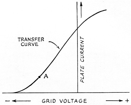
Fig. 1. Plate current vs. grid voltage curve (dynamic characteristic) of a vacuum tube. This curve is linear in the center portion and exhibits deviations at either extremity. The shape of the curve and the choice of the zero-signal operating point (A) will determine the distortion produced by the tube. Mixing action caused by nonlinearity produces distortion products which cannot be eliminated by the tuned circuits of the amplifier.
Shown in the illustration are two frequencies that make up a typical two-tone test signal. In this example, they are 2000 kc and 2002 kc. Now, if the amplifier is perfect, these two signals will be the only ones appearing in the output circuit. An imperfect (but practical!) amplifier will have various combinations of sums and differences of the signals and the harmonics generated by the nonlinear transfer characteristic of the tube. Some of these unwanted products fall within the passband of the tuned circuits of the amplifier and are radiated along with the two test tones.
If the odd-order products are sufficiently attenuated, they will be of minor importance and can be ignored. The sixty-four-dollar question is: Of what magnitude can these spurious products be without becoming annoying? How much "garbage" can be permitted before the signal becomes intolerable to the operator trying to maintain a QSO in an adjacent channel?
The answer to these questions depends upon the type of information being transmitted and the degree of interference that can be tolerated in the adjacent channel. Certain forms of information (not voice) require an extremely low value of spurious products within and adjacent to the passband, otherwise the information will be seriously degraded. Odd-order products greater than 0.001 per cent of the wanted signal may be damaging to the intelligence. Translated into terms of decibels, this means the unwanted odd-order products must be 50 decibels below the wanted signal! This takes some doing, and is orders of magnitude more strict than is necessary in amateur voice communications.
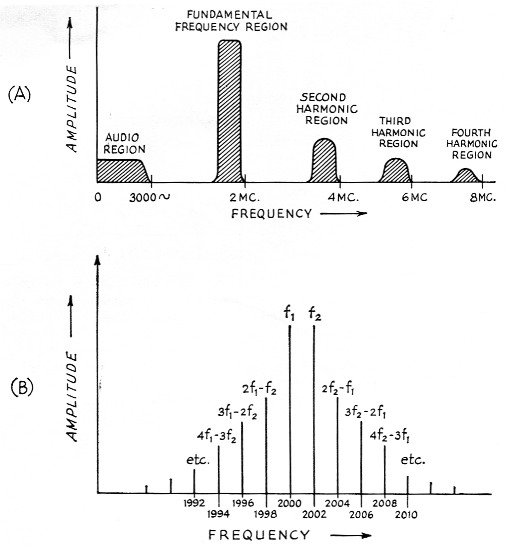
Fig. 2. Intermodulation (mixing) distortion caused by nonlinearity is illustrated by two-tone test signal (f1 and f2). Even-order products (A) are substantially eliminated by the tuned circuits of the amplifier, but odd-order products (B) fall within the passband of the tuned circuits and are not removed. (B) shows the mixture of spurious signals that make up distortion products falling within the fundamental range.
In actual practice, it would seem that if the odd-order products are less than 0.1 per cent of the peak signal power level, the adjacent-channel QRM will be tolerable in everyday amateur communications. This indicates a distortion-product magnitude 30 decibels below the peak output power level of the transmitter. Such a state of affairs can be attained by modern techniques and tubes without too much trouble, provided attention is given to circuit design and operating pafameters of the equipment. Of course, if distortion levels less than this can be reached, so much the better. Unfortunately, some equipments presently operating in the amateur bands and masquerading as "linear" amplifiers exhibit distortion levels of 20 decibels or less below ;peak power output. Use of equipment of this dubious quality quickly reduces the popularity of the operator to zero, and will probably lead to a brick through the shack window if continued!
The grounded-grid linear amplifier
For amateur service, the grounded-grid circuit professes to be the answer to many of the ills besetting the lifiear amplifier. It generally requires a level of drive that is compatible with the great majority of sideband exciters (70 to 100 watts). With proper choice of tubes, it may be operated in a zero-bias condition, eliminating the need for expensive and heavy grid (and screen) power supplies. Neutralization is not usually required. In addition, claims are made that the inherent feedback of the grounded-grid amplifier improves the stage linearity and drops the magnitude of the distortion products. This all sounds too good to be true, and an examination of the grounded- grid amplifier may be in order to see if it is the answer to the sidebander's prayers.
The classic grounded-grid amplifier is shown in Fig. 3. The control grid is at r.f. ground potential and the driving signal is applied to the cathode via a tuned circuit. The control grid serves as a shield between the cathode and the plate, making neutralization unnecessary at medium and high frequencies.
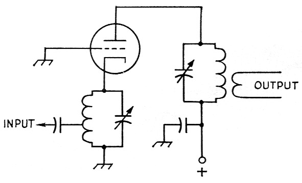
Fig. 3. The grounded-grid amplifier has the input circuit between cathode and ground. The control grid acts as a screen between the plate and the cathode, making neutralization unnecessary in most circuits. The input and output circuits are in series and a portion of the input power appears in the output circuit. The driver stage for the grounded-grid amplifier must be capable of supplying normal excitation power plus the required feed-through power. High-C cathode tank preserves waveform of input signal and prevents distortion.
The input and output circuits of the grounded-grid amplifier may be considered to be in series, and a certain portion of the input power appears in the output circuit. This feed-through power helps somewhat to stabilize the load the amplifier presents to the exciter, and also provides the user with some "free" output power he would not otherwise obtain from a more conventional circuit. The driver stage for the grounded-grid amplifier must be capable of supplying the normal level of excitation power required by the amplifier plus the feed-through power. Stage power gains of 5 to 25 can be achieved in a grounded-grid amplifier.
Measurements made on tubes in the Power Grid Tube Laboratory of Eitel-McCullough, Inc., showed that an improvement of 5 to 10 decibels in odd-order distortion products may be gained by operating various tubes in the grounded-grid configuration of Fig. 3, in contrast to the same tubes in the grid-driven mode. The improvement in distortion figure varied from tube type to tube type, but all tubes tested showed some order of improvement when cathode driven.
The tuned cathode circuit consisted of a bifilar coil, which carried the filament current, and a large-value variable capacitor. The circuit was high-C, with the excitation tap placed to provide a low value of s.w.r. on the coaxial cable to the exciter.
The untuned cathode circuit
After sufficient measurements had been made with the circuit of Fig. 3, the apparatus was modified to simulate the popular untuned cathode input circuit of Fig. 4. It was immediately found that all the tubes tested in the previous circuit gave noticeably poorer results when used with an untuned cathode circuit. Power output dropped by 5 per cent or so, greater grid driving power was required, and linearity suffered to a degree. Specifically, the third-order products rose approximately 3 to 4 decibels over the values produced by the circuit of Fig. 3, and the fifth-order products rose 5 to 6 decibels over those figures recorded with the tuned cathode circuit. The higher order distortion products also rose accordingly. These results were consistent regardless of the type of tube under test, showing that the deterioration was a result of circuit imperfections.
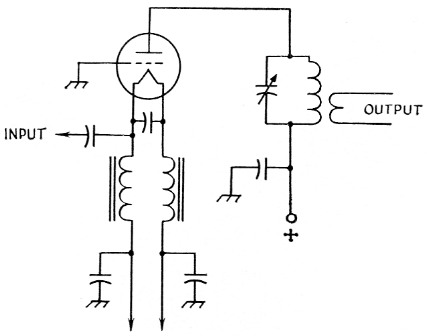
Fig. 4. Popular amateur-style grounded-grid amplifier uses untuned filament choke in place of cathode tuned circuit. Laboratory tests showed that this simplified configuration produced higher intermodulation distortion products and had less power output than the "classic" circuit of Fig. 3, regardless of the type of tube used. In addition, the untuned input circuit proved hard to match and drive with pi-network-type sideband exciter.
Observing the input waveform at the cathode of the grounded-grid amplifier revealed a pronounced distortion of the r.f. waveform, caused by the loading effect over one-half cycle of a single-ended Class-B amplifier (Fig. 5). Plate and grid currents drawn over this portion of the cycle loaded the input circuit. The exciter thus sees a very low load impedance over a portion of the cycle, and an extremely high impedance over the remaining part of the cycle. Unless the output regulation of the exciter is very good, the portion of the wave on the loaded part of the cycle will be seriously degraded, as shown. The exciter used for these tests was operating Class A and was well swamped to improve regulation. Under normal circumstances using an amateur-type exciter, degradation of the input waveform may reach a more serious degree.

Fig. 5. Waveform distortion caused by half-cycle loading at cathode of grounded-grid amplifier can be observed in oscilloscope studies.
Upper left: Two-tone test signal when tuned cathode circuit is used.
Lower left: 3.5 Mc waveform (single tone) from sideband exciter as seen at cathode tank.
Upper right: Two tone test signal when untuned cathode circuit is used.
Lower right: 3.5 Mc waveform (single tone) from sideband exciter, showing severe distortion of waveform when untuned cathode circuit is used.
Obviously, the circuit Q of the exciter output tank at the end of a random length of interconnecting coaxial line is not sufficient to prevent this form of wave distortion. In addition to degrading the intermodulation figure, this waveform distortion also might cause mysterious TVI troubles as a result of the high harmonic content of the wave.
The solution to this problem is to employ either a high-C tuned circuit of the form shown in Fig. 6A, or untuned filament chokes in conjunction with a simple pi-network or tuned circuit as shown in Figs. 6B and 6C. Either arrangement will supply the necessary flywheel effect to retain good r.f. waveform at the cathode of the stage.
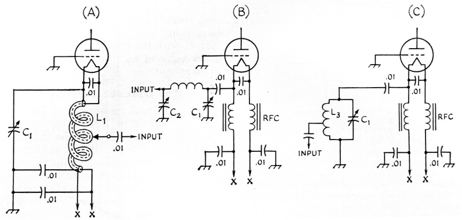
Fig. 6. Tuned cathode network for zero-bias tube may take the form of bifilar circuit (A), pi network (B), or a shunt LC circuit (C). A Q of 5 is recommended for optimum results. However, as this leads to rather bulky circuits at the lower frequencies, the Q may be decreased to 2 or 3 without serious effects. Capacitor C1 is a 3-gang broadcast-type unit. Coils L1, L2, and L3 are adjusted to resonate to the operating frequency with C1 set to about 13 pF per meter of wavelength. Capacitor C2 is approximately 1.5 times the value of C1. The input tap on coils Li and La, or the capacitance of C2, are adjusted for minimum s.w.r. on the coaxial line to the exciter.
Adjustment of the tuned cathode circuit
The cathode circuit is resonated to the operating frequency by means of the variable capacitor. Resonance is indicated by maximum grid current in the amplifier. A low value of s.w.r. on the coaxial line to the exciter is established by adjusting the tap on the tuned circuit, or by varying the input capacitor of the pi network. S.w.r. correction should be made with the amplifier running at maximum input. When the tap is correctly set, maximum grid current and minimum s.w.r. will coincide at one setting of the capacitor. No cutting and trimming of the coaxial line is required, and the exciter will be properly loaded. This is a boon, indeed, to the owners of s.s.b. exciters that have a fixed pi network.
Grid-Current Measurement Measuring the grid current of a cathode-driven amplifier can be exasperating, as it is a ticklish job to "unground" the grid sufficiently to permit a metering circuit to be used yet still hold the grid at r.f. ground potential. The inherent inductance of most bypass capacitors permits the grid circuit to float above ground at some high frequency, and as a result, the amplifier exhibits instability and parasitics. This problem can be avoided by using the measuring circuit of Fig. 7A. The control grid is grounded through a 1-ohm composition resistor, bypassed by a 0.01-µf. disk capacitor. The voltage drop generated by the flow of grid current across the resistor can easily be measured by a millivoltmeter calibrated to read in terms of grid current. Individual grid currents for each of a parallel pair of tubes may be measured by the circuit of Fig. 7B.
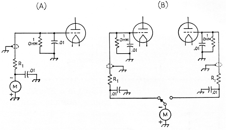
Fig. 7. Grid current in a grounded-grid amplifier may be measured across a low impedance without upsetting the stability of the amplifier.
(A) Grid is grounded by a 1 ohm composition resistor in parallel with a 10 nF ceramic disk capacitor. Resistor and capacitor leads are cut very short, and lead to metering circuit is shielded.
(B) A single meter may be used to measure individual grid currents of two tubes.
The internal resistance of the 0-1 d.c. milliammeter plus the series resistor Ri determines the maximum current that can be measured. Suppose it is desired to read grid current of the order of 60 milliamperes. It would be convenient, therefore, to have the meter read 0-100 milliamperes, as the reading of the meter scale can easily be multiplied by 100 to obtain the actual value of current. Now, when a current of 100 milliamperes flows through 1 ohm, there exists a potential of 0.1 volt across the resistor. Therefore, the meter should read 0.1 volt full scale to correspond to a grid current of 100 ma. Assume the meter has an internal resistance of 55 ohms (such as the Triplett No. 221-T). The voltage drop across the meter itself is 0.055 volts when one milliampere flows through it, but at one milliampere the resistance must be 100 ohms for a voltage drop of 0.1 volt. The difference between 100 ohms and 55 ohms, or 45 ohms, must therefore be added in series with the meter to convert it to read 0.1 volt full scale. On the other hand, the meter by itself across the 1-ohm resistor would indicate 0.055 volts full scale, corresponding to a grid current of 55 milliamperes. If the grid current is below this latter figure no series resistor will be required for the meter. Conversely, higher values of grid current would call for greater series resistance.
Summary
The use of the tuned cathode circuit in a grounded-grid linear-amplifier stage improves linearity, increases the power output, makes the stage easier to drive, and reduces the burden placed on the sideband exciter. It is the firm belief of the authors that the advantages of this circuit are well worth the added cost of parts and the extra controls. It is, of course, possible to dispense with the tuned cathode circuit provided the user understands the handicaps he must assume by omission of this important circuit element.
William I. Orr, W6SAI
Raymond F. Rinaudo, W6KEV
Robert I. Sutherland, W6UOV.