A multioutput variable-voltage power supply
Versatile unit for testing and experiment.
This power unit will supply the voltage requirements, both positive and negative, for most low-power experimental electronic work. Output voltages of both polarities are independently and continuously variable over a wide range by means of panel controls.
The operation of electronic equipment involving vacuum tubes or transistors requires a source of power to supply the various operating voltages. In the case of complete units, such as receivers, amplifiers and test equipment, a power supply is often an integral part of the unit. In such instances, the supply is designed to provide the exact voltages required. I. owever, in experimental work it usually becomes desirable to have an independent power source that is highly versatile to accommodate the many combinations of plate, screen and biasing voltages likely to be encountered. A variable-voltage supply that is inexpensive, and readily adjusted by controls for a wide range of conditions represents the ultimate in convenience for many types of low-power experimental Electronic work.
Circuit
The power supply whose circuit is shown in Fig. 1 is a unit that is suitable for use with any equipment requiring voltages within the range of 0 to approximately 300 at currents up to 200 mA. It is based on a conventional full-wave rectifier circuit utilizing a 600 volt 250 mA center-tapped transformer, T1, a 5U4GB rectifier, and a capacitor-input filter consisting of C1A, L1 and C1B.
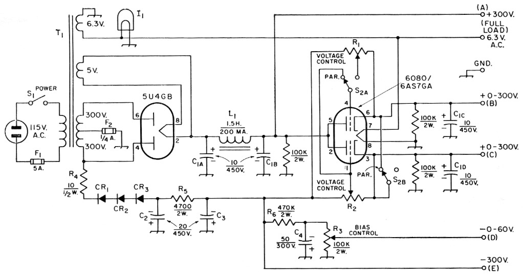
Fig. 1. Circuit of the versatile power supply for experimental work. Capacitances are in µf. and resistances in ohms. Capacitors marked with polarity are electrolytic. Components not listed below are labeled for text reference only.
| C1 | Quadruple 10 µF 450 volt electrolytic. |
| CR1,CR2,CR3 | 130 volt 65 mA selenium rectifier. |
| I1 | 6.3 volt pilot lamp. |
| L1 | Filter choke, 1.5 H, 200 mA (Stancor C-2327). |
| R1,R2 | 2 MΩ, 2 watt control. |
| R3 | 100 kΩ, 2 watt control. |
| S1 | Power switch S.p.d.t. toggle. |
| S2 | Single-triode-to-parallel! switch D.p.d.t. toggle. |
| T1 | Power transformer: 600 volt, 225 mA, c.t.; 5 volt, 3 A; 6.3 volt, 9 A (Stancor P-8164 or similar). |
This versatile power supply furnishes two continuously-variable positive voltages and one negative, in addition to both positive and negative fixed voltages. Components are identified in the text.
The full positive output voltage of the supply (approximately 300 volts at full load) may be taken from Terminal A. Variable positive output voltages may be taken from Terminals B and C, where Cic and Cm provide additional filtering. The variation in output voltage is obtained by means of a type 6080 (or 6AS7GA) dual triode which is used as a variable series resistor. The series resistance represented by the plate-cathode circuit of the tube is varied by adjustment of the grid bias by means of potentiometers R1 and R2.
Switch S2 permits the two triode sections to be used individually to provide two independently-variable output voltages, or to supply a single controlled output voltage with the two sections in parallel when the load current exceeds the maximum value permissible within the plate dissipation rating of a single section. See Fig. 2. A supply of this type tends to be self-regulating at any selected position of the bias potentiometer. If the voltage across the load tends to increase, either as a result of increased line voltage or a decrease in load current, the biasing voltage will also increase, tending to resist an increase in the output voltage.
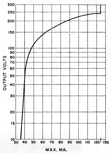
Fig. 2. Curve showing maximum load current permissible at various output voltages, observing the maximum plate-dissipation rating of the type 6080. Curve applies to a single triode section. When two sections are used in parallel, maximum current values shown may be doubled. See text.
Negative biasing voltages are obtained from the same transformer, T1, through a half-wave rectifier using three selenium rectifiers in series (three are required to provide the necessary rectifier voltage rating), and a resistance-capacitance filter consisting of C2, R5 and C3. This section supplies operating bias for the two control potentiometers, R1 and R2. The full output voltage of the negative supply is available for external use at Terminal E. Negative voltage, adjustable from 0 to -60 by means of potentiometer R3, is provided at Terminal D, where C4 and R3 furnish additional filtering.
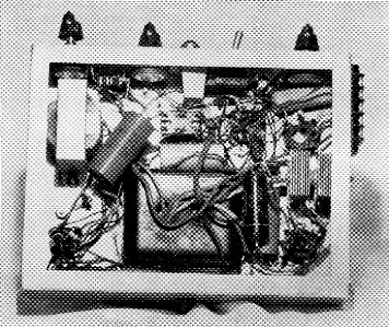
Bottom view of the variable-voltage power supply.
Construction
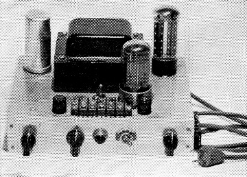
The unit shown in the photographs is built on a 9 × 7 × 2 inch aluminum chassis. The transformer is centered toward the rear, with the rectifier tube to the right and the quadruple 10-pf. filter capacitor C1 to the left. In the foreground are the 6080 dual triode, a 5-terminal barrier strip, and two fuse holders for F1 and F2. The toggle switch behind the terminal strip is S2. The terminal strip carries output terminals for the positive and negative variable voltages, filament voltage and a ground connection. Output terminals for the fixed positive and negative voltages are on a strip fastened to the right-hand end of the chassis.
Along the front edge of the chassis, from left to right, are the two positive-voltage controls, R1 and R2, the pilot lamp, power switch and the negative-voltage control. The selenium rectifiers, filter choke and other small components are mounted underneath. Exact placement is not critical.
Limitations
The plate dissipation rating of the 6080 (13 watts per section) places a limitation on the current that can be drawn from the variable-voltage taps, particularly at the lower voltages. The curve of Fig. 2 shows the maximum current (per triode section) that should be drawn at various output voltages to stay within the dissipation rating. In most low-voltage applications, the current requirements will be within the necessary limits for a single section. The current limits shown in Fig. 2 can, of course, be doubled with the two triode sections switched in parallel. It should he pointed out that Fig. 2 applies only to the case at hand. At higher input voltages, the maximum current to be drawn at the output voltages shown will be less; at lower input voltages, more current (within the maximum current rating of 125 ma. per section) may be drawn by the load without exceeding the dissipation rating of the 6080.
In general, the negative-voltage supply is suitable only for low-current applications, and for biasing vacuum-tube circuits where grid current is negligible. Large currents cannot be drawn from the variable tap (Terminal D) because of the high resistance of the circuit. Appreciable current drawn from Terminal E, or a low resistance from Terminal E to ground (as might be represented by the grid leak of an r.f. amplifier), or appreciable grid-current flow, will alter the bias on the 6080 grids, causing the positive output voltages to change.
Several of these supplies have been built by other amateurs and experimenters and all have worked out very satisfactorily in a wide variety of applications. The smooth variation in both positive and negative voltages makes the supply suitable for use with low-current transistors.
Howard Cohen, K2ITO.