Tapped-coil pi networks
When a pi network is used as the output tank of an r.f. amplifier, it is commonly considered desirable to base the design on a tank Q of 10. Loner values of Q may not provide adequate harmonic suppression or furnish enough flywheel effect for efficient tube operation. Higher values of Q result in greater tank-circuit loss because of the increase in circulating tank current which accompanies an increase in Q. However, the maximum theoretical impedance transformation possible in a pi network limits the output load impedance to a value not less than the plate load resistance divided by the square of the tank Q. Thus for a 50 ohm output load, the Q must be greater than 10 for plate load impedance above 5000 ohms. But, in any event, it is desirable to keep the Q as close to 10 as transformation considerations will permit.
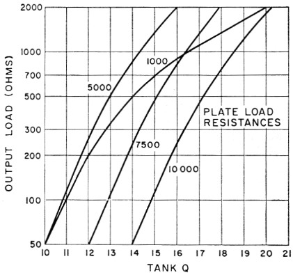
Fig. 1. Curves showing the increase in Q required to obtain a match between various plate-load resistances and output-load impedances with a pi-network when the inductance has a fixed value. The 1000 ohm curve is based on a Q of 10 for a 50 ohm load as the minimum Q desirable for harmonic suppression. The other curves are based on the minimum Q that will provide a match to a 50 ohm load.
If the selected Q is to be maintained over a range of output load impedances, all three circuit elements - input capacitance, inductance and output capacitance - must be capable of adjust-. ment, since only one set of values will produce a match with a single selected value of Q. Earlier forms of pi network made use of a continuously-variable inductor of the roller-contact type. However, in many of the more recent designs, the variable inductor has been dropped in favor of a simpler and less-expensive arrangement using a tapped coil which restricts the inductance to a single value for each band. It should be borne in mind that such circuits are designed primarily for a single value of output-load resistance - usually 50 or 70 ohms - and that higher load resistances can be matched only by allowing the Q to vary.
From the considerations mentioned above, it is of interest to know in which direction the Q must vary and by how much. A series of calculations produces the curves shown in Fig. 1. This graph shows how the Q must vary to match various plate-load resistances to output loads of higher value than 50 ohms when the network is designed basically for minimum permissible Q at 50 ohms. The curves show that an increase in Q is required as the output-load impedance increases. They also show that for the same basic Q at 50 ohms, the increase in Q required is greater for lower values of plate-load resistance.
To what degree does this increase in tank Q affect tank-circuit loss? Tank current increases directly as the tank Q and, with a coil of fixed resistance, tank-circuit loss increases as the square of the tank current. The curve for a plate-load impedance of 1000 ohms shows that a match to a 2000 ohm load requires doubling the tank Q. The tank-circuit loss therefore increases by a factor of four. If the loss at Q10 is 5 per cent, it will increase to 20 per cent at Q20. At higher plate-load resistances, the necessary increase in Q is somewhat less.
In terms of dB, the increase in tank-circuit loss is not of too serious consequence. However, there are other practical considerations. It takes a surprisingly small amount of power loss in a tank coil to cause the coil to run hot. An increase of 3 or 4 times in tank-coil dissipation may be sufficient to damage a plastic-supported coil unless the conductor size is generous and the coil well ventilated. High-Q circuits also require more-frequent retuning in covering a band of frequencies. But perhaps the most serious problem is that the tank capacitor must have considerable reserve capacitance. If the Q must be doubled to obtain a match at the higher load impedances, the tank capacitance must be doubled. Providing this reserve capacitance may not be a problem at the higher frequencies, but if 80 meters is to be included, the capacitor required for this band may not only present a space problem but its minimum capacitance may be so high that there will be difficulty in holding the Q down to a value that will permit reasonable tankcircuit efficiency at the higher frequencies. In some cases, the latter problem has been met by providing a dual capacitor, one section only of which is used for the higher frequencies.
These difficulties may be overcome, of course, by the use of an additional network, such as an antenna coupler, which may be adjusted so that the load presented to the output circuit of the transmitter is a constant value regardless of the actual impedance represented by the antenna. An antenna coupler also provides the means for compensating for reactive components that so often make "random"-type antennas so difficult to handle directly with a pi network.