Transistorized auditory "grid-dip meter"
Wide ramge battery-operated test oscillator.
Names fail us, in trying for a moniker for this unit, since it has no grid and no meter to dip. Nevertheless, it does ff the work of a grid-dip oscillator, with the added convenience that you don't have to look at it while you're checking a circuit. Originally described in The Braille Technical Press for January of this year, we think it has just as many advantages for those with normal sight as for those without.
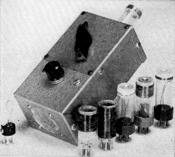
The meter with its set of coils covering 2 to 220 Mc. The plastic indicator under the tuning knob has the usuul 10-scale intervals marked with Braille characters, but could readily be equipped with an ink scale. The small speaker for auditory indications is mounted on the near end of the box. The power consumption is 5 mA at 9 volt.
Here is a portable battery-operated grid-dip oscillator with a frequency range of 2 to 220 Mc, measuring only 5¼ inch long, 3 inch wide and 2_1/8 inch thick, with built-in 9-volt battery supply and auditory indicator circuit. The auditory indicator is a "must" for the blind technician; for the sighted, it is a convenience which allows him to check the g.d.o. without bothering to look around at the meter movement.
The circuit is built in a small two-piece aluminum box (LMB type 136) with the half containing the two end aprons holding the instrument; the other half, with the two long side aprons, serves as the bottom cover. A 1½ inch p.m. speaker is centered on one end apron, with the coil socket centered on the opposite one. The tuning capacitor is mounted on the top of the case about 1½ inches from the end apron containing the coil socket. The sensitivity (pitch) control is mounted about 1½ inches from the other end apron. The pitch control is fitted with the on-off switch, thus cutting down on the number of controls and allowing more space for a dial scale. In the unit built here at W2JIO the dial is Brailled, although an ink scale can easily be fashioned. The output transformer for use in connection with the auditory indicator is mounted on the end apron beside the speaker. The bottom half of the box contains the clamp for holding a 9 volt battery in place, and this half is also fitted with four small feet.
If a visual meter movement is used, much of the electronics may be omitted, with the oscillator simply coupled to a diode, a potentiometer (used as a rheostat) for setting the meter reading, and a small 50-100 microammeter. But if you've never tried an auditory indicator you'll be very pleasantly surprised at the ease of operation provided by this device.
Auditory indicator
The auditory circuit makes use of the transistorized "Auditory Gimmick" described in so much of the equipment designed for blind technicians. Basically, it is made in the form of a simple Hartley oscillator, Fig. 1, using a p-n-p transistor (2N107), with an n-p-n (2N35) connected as a d.c. amplifier control circuit to vary the bias (and hence the frequency) in accordance with changes in energy coupled to the base of this d.c. amplifier. Energy is coupled from the r.f. portion of the instrument through a small capacitor, and is rectified by a shunt-type diode whose output feeds into the sensitivity-control potentiometer. The greater the energy the higher the pitch, and vice versa.
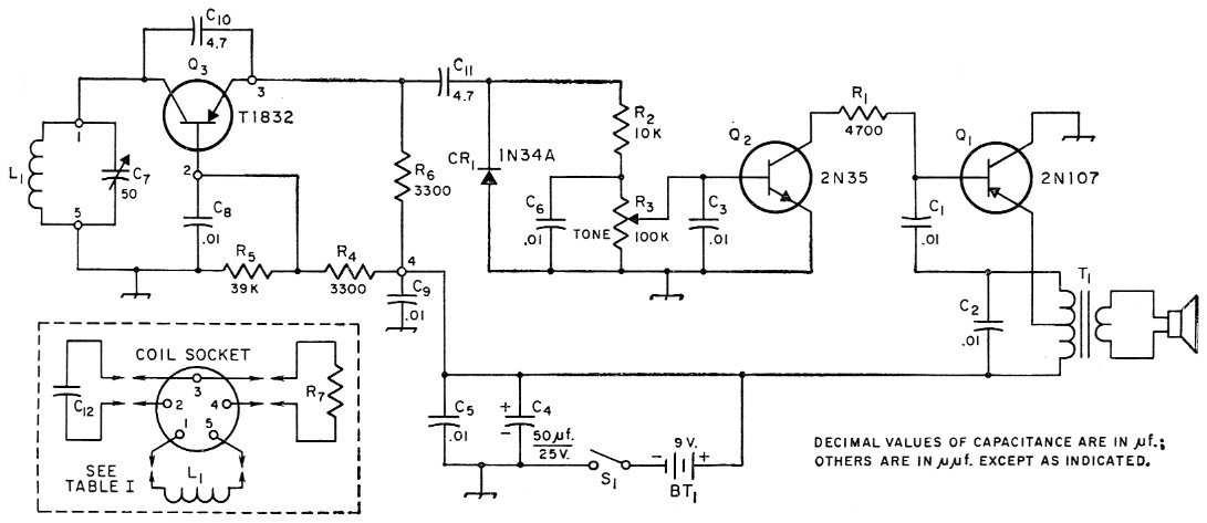
Fig. 1. Circuit diagram of the auditory grid-dip oscillator. Resistances are in ohm, resistors are ½ watt composition. Numbered terminals in r.f. oscillator circuit refer to pin numbers on coil socket.
| BT1 | 9 volt transistor battery (RCA VS-323). |
| C1 | Paper. |
| C2,C3,C5,C6,C8,C9 | Disk ceramic. |
| C4 | Electrolytic. |
| C7 | 50 pF variable (Hammarlund HF-50). |
| C10,C11,C12 | Tubular ceramic. |
| L1 | See coil table. |
| R3 | 100 kΩ control, linear taper. |
| S1 | S.p.s.t. toggle, mounted on R3. |
| T1 | Transistor output transformer, 500 ohm c.t. to 3.2 ohm (Stancor TA-42 or Philmore ST-32). |
| Loudspeaker is a 1½ inch speaker (Lafayette Radio SK-61). | |
The indicator circuit in this unit is built on a standard 7-pin miniature socket which serves as a multiple tie-point assembly for the entire circuit - resistor R1, capacitors C1 and C2, the two transistors, and the leads from the small output transformer T1. The socket is mounted to the chassis by running a 4-36 machine screw through the center hole, and mounting it to the top of the box. The low-impedance secondary of the transformer is taken directly to the speaker terminals. A single tie point is fastened to one of the speaker's mounting screws for B positive, and this point is bypassed both for r.f. and low-frequency energy by C4 and C6 in parallel.
The germanium diode, isolating resistance R2, and the r.f. bypass capacitor C6 are all supported by the potentiometer (R3) terminals.
R.F. oscillator
The r.f. oscillator has gone through a number of changes in the course of arriving at the circuit shown, beginning with an RCA 2N247, which gave a maximum frequency of about 90 Mc, then the RCA 2N384, which got us up to about 135 Mc, and finally the Philco T-1832 (2N1742) which makes the instrument work extremely well up to 220 Mc. Actually, a higher frequency is easily possible - we just didn't bother to try going much higher with this particular layout because the design of the tuned circuit didn't lend itself to u.h.f. The emitter, base and collector of the r.f. transistor, Q3, are mounted directly to the pins of the coil socket, to keep lead lengths to a minimum. The remaining two pins of the coil socket are used for the lower end of the tuned circuit and for B positive.
The oscillator has the p-n-p transistor connected in the common-base arrangement, with the tuned circuit connected between the collector and ground (base), a resistance inserted in series with the emitter, and with a feedback capacitance connected from emitter to collector. A word or two about the design problems involved in the oscillator portion of the circuit might be in order, since changing transistors necessitated some slight circuit modifications which should be of interest.
The original circuit design with the 2N247 drift transistor used a feedback capacitor of 10 pF, with an emitter resistor of 4700 ohm at the lower frequencies, and 220 ohm at the higher frequencies. We found that for some reason the circuit refused to oscillate at the low frequencies, particularly with the tuning capacitor set near the maximum-capacitance end of its range. We suspected, and rightly too, that the feedback capacitance was insufficient, and so added another 15 pF in the two low-frequency coils, after which the circuit worked fine. The 2N384 drift-field transistor behaved about the same, except that it oscillated at a higher frequency (135 Mc.).
When we installed the Philco T-1832 (2N1742), whose maximum oscillation frequency is 1300 Mc, we found an entirely different state of affairs. The circuit performed very well at the higher frequencies, but at the lower frequencies, and at frequencies in the vicinity of 10 to 20 Mc, with the tank capacitor nearly fully meshed, oscillations ceased. Increasing the feedback capacitance from collector to emitter helped slightly, but the circuit would still fall out of oscillation with the tuning capacitor completely meshed. The addition of a small capacitance shunted from emitter to base did the trick, and the drop-out no longer occurs. This extra shunt capacitance probably provides some necessary phase correction at the lower frequencies. The necessary additions in circuit capacitance are easily handled through the use of additional capacitors mounted inside the coil forms, so that simply plugging in the coil changes the capacitance to the desired value.
The output of the oscillator at the lower frequencies is quite high - so high that it provides too much excitation for the auditory part of the circuit. Therefore, a higher value of emitter resistance is used at these frequencies, with a smaller shunting resistance added at the higher frequencies (above 54 Mc.). This is also accomplished through the use of spare pins on the coil forms.
Coils are wound on Amphenol type 24-5H polystyrene coil forms. The socket for the coils (Amphenol 78-S5S) is used to support the components, including the high-frequency transistor. No. 14 solid wire leads run to the tuning capacitor, which is mounted on a slant to give very short connecting leads to the coil socket. Mount the socket so that Pins 1 and 5 face the inside (top) of the box. This results in the shortest lead lengths to the tuning capacitor.
The specifications for making the coils are given in Table 1. If any difficulty is experienced in finding the small polystyrene coil forms, it may be necessary to make your own. This is very simple: Obtain a piece of ¾ inch o.d. polystyrene tubing and cut it into 2 inch length. Use Amphenol 5 prong plugs, No. 91-MPM-5L. Remove the metal cap and fit the bakelite plug into the tubing, fastening it with cement and the retaining screw used to hold the metal cap in place.
| Coil No. | Freq. Range Mc | Wire* Size | Turns | Remarks |
|---|---|---|---|---|
| 1 | 2.15 - 3.6 | 28 | 95 | Close-wound. C12 100 pF mica. |
| 2 | 3.2 - 6.8 | 28 | 48 | Close-wound. C12 33 pF mica. |
| 3 | 6.6 - 13.6 | 24 | 22 | Close-wound. C12 10 pF mica. |
| 4 | 13.0 - 27.4 | 24 | 9¼ | Spaced over ¼ inch length. C12 4.7 pF mica. |
| 5 | 25.0 - 54 | 24 | 4¼ | Spaced approximately wire diameter. C12 10 pF mica. |
| 6 | 45 - 90 | 24 | 1½ | Spaced wire diameter. C12 10 pF mica; R7 220 ohm. |
| 7 | 90 - 220 | 14 | Hairpin loop, sides spaced approx. 1/8 inch, length 1¾ inch including coil pins. C12 10 pF mica; R7 220 ohm. | |
| *Enameled wire. Coil forms ¾ inch diameter; Amphenol 24-5H or equivalent. See text for alternative homemade forms. Coil socket is Amphenol 78S5S. | ||||
| Note: If the audio tone tends to jump at some point instead of varying smoothly in pitch as the tuning capacitance is varied, try changing the value of C12. | ||||
For frequencies above 54 Mc, the emitter resistance is too high and the circuit will not oscillate satisfactorily unless this value is reduced. Therefore, an emitter shunting resistor is used. If higher-frequency coil units are used, remember this shunting resistance.
After building this unit and playing with it for some time, our only regret is that we didn't take the trouble to build an instrument for the very-high frequencies, using high-frequency techniques. The long rotor tab and high minimum capacitance in the tuning capacitor precludes the use of the instrument at the high frequencies.
However, perhaps someone can now take the time to investigate this circuit at frequencies up to 500-1000 Mc or better.
Some time ago, T.V. Cranmer, K4MMB, of Frankfort, Kentucky (a Braille Technical Press reader) built an instrument of this type, although its construction was considerably different and its frequency range was only up to 50 Mc. Tim's experience with this circuit gave us the encouragement to build ours, and we wish to thank him here.
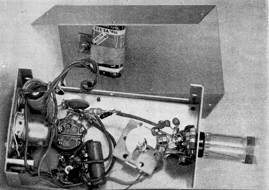
Inside the meter. Every. thing except the battery is mounted on one piece of the two-piece box. Most of the r.f. oscillator components are mounted On the coil socket. A 7- prong tube socket, lower left, is used as a multiple tie-point assembly for the small audio components.
Robert W. Gunderson," W2JIO.