Coaxial switch performance
Design and construction of basic types.
With reasonable attention to the details discussed here, most of the simpler conventional coaxial-cable switches can be made to perform well over the range of 30 to 300 Mc. Included are tabulated results of measurements made on typical homemade and manufactured types.
Coaxial-cable switches, manually or electrically operated, add much to the convenience and efficiency in operating today's modern amateur station. They facilitate band changing in this era of multiband operation. They can perform a change-over function allowing the use of one antenna for receiving as well as transmitting. Electrically actuated (relay) types can be used as remote switches to economize in the use of coaxial cable when several antennas are mounted on the same or adjacent supports. Coaxial switches also simplify station operation by providing a convenient means of switching final amplifiers, v.s.w.r. monitors, converters, and the like, in and out of a transmission line. In elaborate antenna systems they may also be used to control radiation patterns by switching phase-shifting cables in and out of a feeder system.
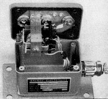
Photo of the relay switch sketched in Fig. 1 showing the copper-strip connections and weather-proof enclosure.
Most hams seem reluctant to build their own coaxial switches and rely instead on the available commercial or surplus variety. This hesitancy apparently stems from the lack of familiarity with the factors and problems involved in the design and construction. Since the commercially-available units may not always be completely suited to a particular ham's requirements, this article will outline some of the considerations requiring attention. This information should enable the ham to design switches to meet his station requirements instead of altering or restricting the station complement to fit available switching units.
Representative types
Coaxial transmission-line switches may run the gamut from the crudest type of toggle or knife switch, or relay, to designs of extreme mechanical and electrical sophistication. At frequencies up to 30 Mc, most simple switch designs will perform adequately. Small relays, wafer switches or solenoid-actuated "flapper"-type switches perform well. At frequencies above 300 to 400 Mc, the performance of most simple switch designs, as well as of the UHF-type of cable connector commonly used by amateurs, becomes unsatisfactory for most requirements. Adequate disconnected-channel isolation becomes difficult to achieve and special techniques beyond the scope of this article must be employed to compensate for the effects of unavoidable dimensional changes. Between these two extremes lies the frequency range of 30 to 200 or 300 Mc, which includes the amateur v.h.f. bands. The material presented here is principally in reference to this region.
Design considerations
In the v.h.f. range, most of the previously-mentioned basic types of coaxial switch will perform well if some attention is paid to insure that the characteristic impedance of the switch, considered as a short section of line, is reasonably close to the 50 or 70 ohms of the line used, and that gross line discontinuities are eliminated. (A "discontinuity" is an abrupt change in transmission-line dimensions or direction resulting in distortion of the electromagnetic-field configuration.)
Just how does one determine whether or not a given switch design is suitable? In answering this question, there are three important considerations. One of these is the characteristic impedance and/or physical discontinuity, just mentioned, which may result in an increase in the v.s.w.r. on the line connecting the switch to the transmitter. This is of consequence not only as it affects the losses in the section of line connecting the switch and transmitter, and the transformed load impedance presented to the transmitter output circuit, but also because it may result in higher voltage or current at the switch contacts. In a typical switch of good design connected to a perfectly matched antenna feed line, the switch may cause a v.s.w.r. of 1.2 to 1 on the line to the transmitter.
A second consideration is circuit isolation. This concerns the amount of r.f. energy or "crosstalk" coupled from an operating circuit to a circuit disconnected by the switch. Isolation is usually expressed in terms of dB. If the isolation is given as 60 dB, it means that one millionth of the power in the operating circuit is being coupled into the disconnected circuit. For a given switch design, isolation will, of course, vary widely with frequency. An isolation of 30 dB is usually acceptable for amateur requirements.
The third consideration is insertion loss. This is the difference between the power fed to the switch and the power fed to the line from the switch. This loss is made up of dielectric loss in the switch insulating material and resistance loss at the switch contacts. Either one loss or the other will increase with an increase in v.s.w.r. A typical switch may have an insertion loss of 0.2 dB or less.
Unfortunately, measurement of all, or even one, of these vital characteristics is not possible with the test equipment available to most hams. Therefore test data on the switches described herein, as well as on some commercially available units, have been taken by the author, using specialized laboratory equipment, and the results are included in tabulated form. Data for operation at frequencies below 30 Mc are not shown specifically because in all cases the performance is substantially the same, or better, than that shown for 30 Mc.
Constructional details
A sketch of a relay-type switch is shown in Fig. 1. The switching element is a small general-purpose relay. Additional design features can be seen in the photograph. One important item in the design of this unit is the wide copper strap joining the connector center-conductor and relay terminals. This increases capacitance to ground which helps to maintain a more constant characteristic impedance and thus decreases the switch v.s.w.r. The switching time measured is the same as that of the relay. In typical examples, a unit switched in 10 to 11 milliseconds.
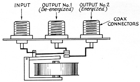
Fig. 1. Relay-type switch of the s.p.d.t. type for coaxial cables. The r.f. path is shown in heavy lines. The relay is a small general-purpose type.
The unit shown in the photo is designed for outdoor use and therefore it has been suitably sealed against the elements. A sealing gasket and special precautions regarding the UHF-type connector, to be discussed later, are necessary. The performance of this unit is given in Table I.
| Freq. (Mc) | V.S.W.R. | Isolation (dB) | Insertion Loss (dB) |
|---|---|---|---|
| 30 | 1.02 | 45 | < 0.1 |
| 50 | 1.04 | 41 | < 0.1 |
| 150 | 1.2 | 33 | < 0.1 |
| 225 | 1.3 | 30 | 0.1 |
A somewhat different design is shown in Fig. 2. This is a "flapper" type, essentially like one designed by W1QVF and described in QST for July, 1956. Its characteristics are compiled in Table 2.
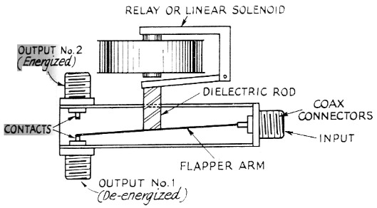
Fig. 2. Relay- or solenoid-actuated "flapper"-type switch. Note contacts mounted on coaxial connectors.
| Freq. (Mc) | V.S.W.R. | Isolation (dB) | Insertion Loss (dB) |
|---|---|---|---|
| 30 | 1.04 | 53 | Not measured |
| 50 | 1.04 | 48 | Not measured |
| 150 | 1.19 | 32 | Not measured |
| 225 | 1.34 | 31 | 0.1 |
| * Type UHF connectors. | |||
Switches of the two preceding forms are of the single-pole double-throw variety. They find wide use in antenna change-over operations and in selecting one of two available antennas in both mobile and fixed-station use. They may also be used in multiple to accomplish more complicated switching functions.
A switch of the rotary multiposition type is sketched in Fig. 3. The switching element is a ceramic wafer switch. A switch of this type furnishes two or more output positions from a single input. Measurements on this switch are shown in Table 3. A switch of similar construction, but with different circuit arrangement, is shown in Fig. 4. This is basically a d.p.d.t. switch, the electrical configuration being shown to the right of the sketch. Such a switch is useful in switching any device such as a final amplifier, converter, or s.w.r. indicator, in or out of a transmission line. Still other varieties of wafer-switch design were described by W9ERU in an earlier issue of QST.(1)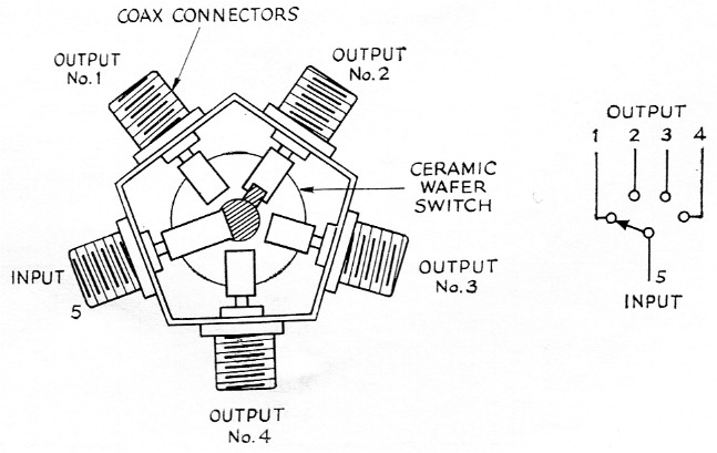
Fig. 3. A single-pole four-position rotary switch with mounting for five connectors. Switch is ceramic-wafer type. Equivalent circuit is shown at right.
| Freq. (Mc) | V.S.W.R. | Isolation (dB) | Insertion Loss (dB) |
|---|---|---|---|
| 30 | 1.02 | 48 | Not measured |
| 50 | 1.03 | 45 | Not measured |
| 150 | 1.1 | 36 | Not measured |
| 225 | 1.14 | 33 | Not measured |
| 435 | 1.24 | 27 | Approx. 0.5 |
| *Maximum measured on any channel. Type UHF connectors; ceramic wafer. | |||
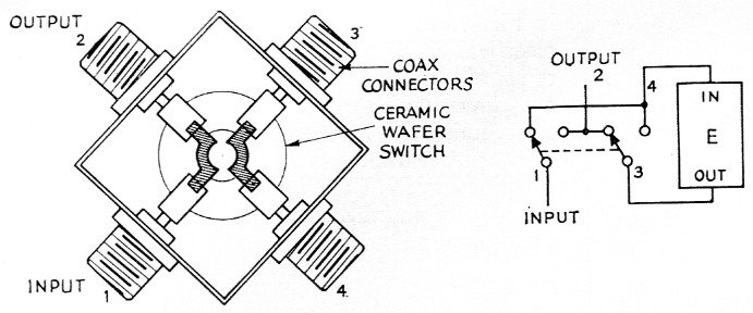
Fig. 4. Transfer-type switch. Equivalent circuit is shown at right. This arrangement is suitable for switching any device (E), such as an amplifier, converter or s.w.r. indicator, in series with a line connected at 1 and 2.
Table 4 shows measured data on three typical manufactured switches.
| B & W 550-A (Rotary) | |||||||
|---|---|---|---|---|---|---|---|
| Freq. (Mc) | V.S.W.R. | Isolation (dB) | Insertion Loss (dB) | ||||
| Ch. 1* | Ch. 2* | Ch. 3* | Ch. 4* | Ch. 5* | |||
| 30 | 1.02 | 48 | |||||
| 50 | 1.03 | 45 | |||||
| 150 | 1.1 | 36 | |||||
| 220 | 1.02 | 1.1 | 1.14 | 1.08 | 1 | 33 | |
| 435 | 1.08 | 1.2 | 1.24 | 1.16 | 1.04 | 27 | Approx. 0.5 |
| *Progressing clockwise from input connector, as viewed from shaft side. | |||||||
| Bay-Roy Electronics CU-421 (S.P.D.T. Relay) | ||||
|---|---|---|---|---|
| Freq. (Mc) | V.S.W.R. | Isolation (dB) | Insertion Loss (dB) | |
| Pos. 1* | Pos.2* | |||
| 30 | 1.02 | 1.02 | 45 | < 0.1 |
| 50 | 1.02 | 1.04 | 41 | < 0.1 |
| 100 | 1.04 | 1.19 | 35 | < 0.1 |
| 150 | 1.05 | 1.2 | 33 | < 0.1 |
| 200 | 1.1 | 1.32 | 30 | < 0.1 |
| 225 | 1.1 | 1.3 | 30 | 0.1 |
| *Position 1, relay unenergized; Position 2, relay energized. | ||||
| Advance CB/1C2C/115 VA (S.P.D.T. Flapper) | ||||
|---|---|---|---|---|
| Freq. (Mc) | V.S.W.R. | Isolation (dB) | Insertion Loss (dB) | |
| 30 | 1.04 | 53 | ||
| 50 | 1.04 | 48 | ||
| 100 | 1.12 | 42 | ||
| 150 | 1.19 | 32 | ||
| 230 | 1.34 | 31 | 0.1 | |
Actuators
While manually-operated switches have many uses, relays or other types of electrically-actuated switches have the advantage that the actual switching operation can take place at the most appropriate point regardless of its remoteness from the operating position. Also, switching is virtually instantaneous, which is a requirement in any break-in system. Relays and solenoids are available with actuating coils designed for a variety of standard a.c. and d.c. voltages, so that the most convenient source may be used. Rotary switches are also available with solenoid-operated ratchet mechanisms that permit remote control of the switch.(2) In his article,(1) W9ERU describes a motor-driven unit with an automatic position stop.
Coaxial connectors
The coaxial connectors used in constructing switches are an important consideration. The type UHF connector in popular amateur use performs in a satisfactory manner at frequencies up to 300 or 400 Mc. if the switch is confined to an indoor environment. They may also be used under mild outdoor conditions, as might be encountered where some protection against the elements is afforded. However, they have no specific provision for sealing against moisture and therefore they should be inspected periodically to see that moisture seepage has not taken place. When the switch must be exposed fully to the effects of weather, special precautions should be taken. One technique is to coat the mating connector surfaces with silicone grease prior to assembly of the connector pair. Another procedure is to wrap the mated pair with plastic electrical tape. This is effective and makes use of a material commonly found in the ham shack. Both techniques may be applied simultaneously to advantage, of course. The type UHF chassis-mounting receptacle used in the construction of switches carries the military designation of SO-239, 49194 (Amphenol 83-1R). The mating cable plug is identified by the number PL-259, 49190 (Amphenol 83-1SP) for ½ inch coax cable, such as RG-8/U, or UG-111/U (Amphenol 83-750) for ¼ inch cable, such as RG-58/U.
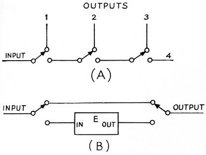
Fig. 5. Diagram showing how s.p.d.t. switches or relays may be combined to perform the functions of rotary switches. A shows a combination performing the functions of the switch of Fig. 3. The arrangement of B is essentially equivalent to the switching circuit of Fig. 4.
A superior series of connectors is the N series. These connectors have the following advantages:
- They employ constant-impedance design and hence provide superior r.f. performance, especially at the higher frequencies.
- They have moisture-sealing features as an integral part of the design and therefore no special measures are required in using them in severe outdoor environment.
- They can be assembled to the coaxial cable without the need for soldering the outer braid to the connector body. This simplified procedure eliminates the danger of melting the cable dielectric while applying solder. Table 4 lists several of the various fittings available in the N series, while Table V shows fittings that permit transition between type N and type UHF fittings.
Although new type N connectors are more expensive than corresponding UHF-type units, they can often be found on the surplus market for less than the cost of new UHF-type connectors.
The names and terms associated with the various connectors listed in Tables 5 and 6 are those commonly used in the connector field. The "sex" of a connector is determined by the nature of the center of the center-conductor termination For example, a plug-type connector is one that has a male center-conductor termination and a clamping mechanism to attach to a coaxial cable. A jack has a female center-conductor termination and a clamping device to attach a coaxial cable. An adapter is a device which mates with two connectors and does not have provision for attaching directly to a coaxial cable. A chassis receptacle is a connector with a female center-conductor termination and employs a flange to allow fastening to a chassis or plate.
| Mil. Type | Function |
|---|---|
| UG-21D/U | Plug (male, fits -inch coax cable (RG-8/U) |
| UG-23D/U | Connector (female), fits RG-8/U |
| UG-27C/U | Right-angle adapter (male to female) |
| UG-28A/U | Tee adapter (all female) |
| UG-29B/U | Straight adapter (female to female) |
| UG-57B/U | Straight adapter (male to male) |
| UG-58A/U | Chassis receptacle |
| Mil. Type | Function |
|---|---|
| UG-83A/U | Mates type N male and type UHF receptacle |
| UG-146/U | Mates type N female and type UHF plug |
| UG-318/U | Mates type N female and type UHF receptacle |
Notes
- Hubbell, "Switching coaxial feed lines," QST, October, 1960.
- Wenner, "Remotely-controlled coaxial switch," QST, August, 1958, "Hints & Kinks."
Harold J. Braschwitz, W8YPT.