A utility power supply made from an old TV set
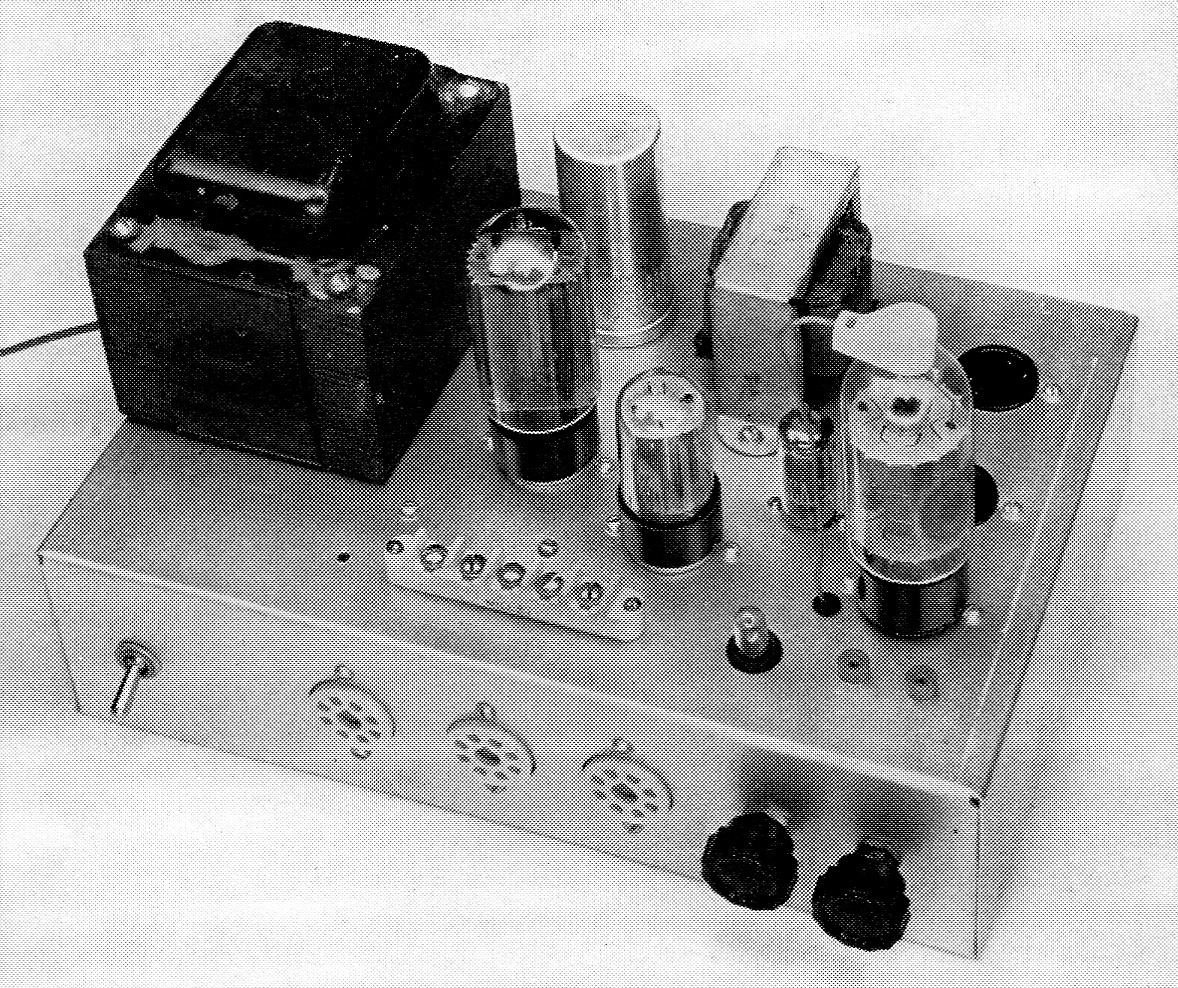
The switch at the left front of the chassis is S1. In the center are three octal power take-off sockets. The control adjacent to the sockets is R4 and R5 is at the right. Along the top front of the chassis is the five-terminal 6.3 volt strip, the NE 51 which is mounted in a rubber grommet, and J1 and J2, tip jacks. The two empty sockets at upper right corner are for VR tubes as explained in the text.
Any amateur interested in building his own gear will find that a very handy item to have in his station is a utility power supply. In many instances a ham is reluctant to build station accessories such as converters, monitors, and so forth because a good part of the cost in such units is in the power supply. The supply to be described here has enough power capabilities to handle all the accessories that even the most ambitious builder could dream up. In addition, the cost of the supply is so low that surely any reader can afford it. Recent articles(1) have shown the appeal of using old TV chassis for a ready-made junk box and that is the basis for the supply to be described.
Circuit features
The circuit diagram for the utility supply is shown in Fig. 1. Basically, the circuit consists of full-wave rectifier, V1, into a capacitor-input filter circuit. The filter circuit is made up of C1, L1, and C2. With most TV transformers the d.c. output voltage will be between 300 and 400 volt at full-load current. The average TV transformer should handle about 250 mA current drain in continuous service without overloading.
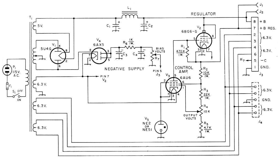
Fig. 1. Circuit diagram of the utility power supply. All resistances are in ohms, resistors are one watt.
| C1,C2 | 10 or more µF, 450 V electrolytic, see text. |
| C3,C4 | 20 µF, 450 V electrolytic. |
| F1 | 3 A fuse |
| J1,J2 | Tip jacks. |
| J3 | Octal tube socket. |
| J4 | 5 terminal binding post strip (Millen 37305). |
| L1 | Approx. 2 H, taken from TV set. |
| P1 | A.c. line plug. |
| R4 | 10 kΩ control. |
| R7 | 1 MΩ control. |
| S1 | Single-pole, single-throw toggle switch. |
| T1 | Power transformer taken from TV set, see text. |
With the transformer used in this supply the a.c. high voltage measures 330 volt each side of the center tap. The no-load d.c. voltage out of filter is slightly more than 400 volt. Under a load of 50 mA the voltage drops to 380, and is down to 290 volt at a load of 250 mA. Other transformers with different ratings will of course give correspondingly different outputs, but these figures are typical of what you may expect from a TV power transformer.
Taking off from the output of the filter network is a regulating circuit that will provide a regulated voltage that can be set anywhere from 235 volts down to 90 volts. The amount of current that can be drawn at the different voltages is shown and explained in Fig. 2.
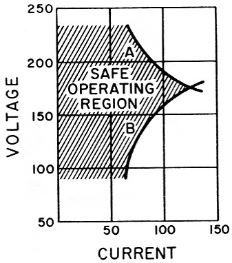
Fig. 2. This graph shows the maximum current that can be drawn in the regulated range, at voltages from 90 to 235, using the circuit of Fig. 1. Curve A shows the maximum amount current at which regulation will be maintained. Curve B shows the the current, at any given voltage, at which the plate dissipation of the 6BG6G regulator tube is just at the tube rating. Operation should be confined to the region to the left of both curves. For example, at 150 volt you could take as much as 150 mA at constant voltage, but this would be well over the safe rating of the regulator tube. To stay within the tube limits the maximum safe current would be 75 ma., as shown by curve B. These curves apply only to the circuit and components shown in Fig. 1, although they will be fairly typical of regulated supplies' constructed of other components of the same approximate ratings.
The tubes used in the regulator circuit, V2 and V3, are a 6BG6G and a 6AU6 respectively. These were taken from the old TV chassis and served the purpose adequately. The 6BG6G is connected in series with the load circuit and acts as a voltage regulator. The 6AU6 serves as the control tube; its plate current flows through R3, and the voltage drop across this resistor is used to bias the regulator tube, V2, which acts as an automatically variable resistor in series with the load. The plate current of V3 is controlled by R4, which is used to adjust the bias on the control tube. If this bias is changed, there is a corresponding change in the current flow through the control tube. This in turn changes the voltage drop across R1, thus controlling the bias on the regulator tube. When the bias on V2 becomes more negative, the plate-to-cathode resistance of the tube increases, thereby lowering the output voltage. When the bias on the regulator tube goes in the opposite direction the plate-cathode resistance is decreased and a higher output voltage is obtained. Good regulating action requires a constant-voltage bias source for the control tube. This is provided by V5, a neon bulb, which establishes a "reference" voltage for the cathode of V3.
In an unregulated supply an increase in load (heavier current drain) will cause the voltage to drop. With this system of electronic regulation any change in output voltage, from whatever cause, changes the effective plate-to-cathode resistance of the regulator tube in such a way as to compensate, thus to holding the output voltage constant. The regulated voltage out of V2 can be held quite accurately over the voltage/current range shown in Fig. 2.
In addition to the unregulated and regulated positive voltages available from the supply an adjustable negative voltage source is provided. This consists of a half-wave rectifier, V4, into a capacitor-input type filter and a voltage divider, R7. The voltage range is from 0 to about 400 volt negative, the higher limit depending on how heavily the positive supplies are loaded. This type of negative voltage source is not capable of handling more than one-half milliampere of current. However, it is useful whenever a negative voltage at low current requirements is needed, as in grid-block keying and in many biasing applications.
To provide for flexibility an extra pair of octal sockets is mounted on the chassis. These could be used, for example, for voltage regulator tubes of the gas type if a fixed regulated voltage is needed.
In the unit shown in the photographs there are several different power take-off connections. Two separate 6.3 volt a.c. sources (these can be connected in series to provide 12.6 volt), +B regulated, and negative voltage, are available through parallelled octal sockets. The builder can install as many sockets as he thinks he'll need - just connect all the same-numbered pins together. Three are used here. In addition, there are two tip jacks which can be used for the regulated and unregulated +B voltages. A five-terminal strip mounted on top of the chassis is used for two 6.3 volt take-offs; the remaining terminal can be used as the builder desires.
Getting the parts
The best source of old TV sets is your local TV repairman or dealer. You'll find that he is usually very happy to unload the chassis at prices of a couple dollars each or, in some instances, just for the asking. If the chassis you get doesn't have any tubes in it you can probably get used tubes for the supply from the same source, for pennies. When getting the old set, make sure it has a power transformer - some of the sets used selenium rectifiers in transformerless supplies.
In stripping the parts from the set keep all component leads as long as possible. If you have a voltmeter you can check the different windings on the power transformer. The primary winding leads on the transformer are usually the two black leads. If you are in doubt, or if you don't own or can't borrow a multirange a.c. voltmeter, you might be able to impose on the TV repairman's good nature and get him to check out the transformer for you. The two controls, R4 and R7, can be found in most sets, along with the electrolytic capacitors and resistors needed.
In nearly all TV transformers one of the 6.3 volt filament windings is designed to carry much more current than the other windings. This winding can be determined by the size of the conductor or conductors if the leads are stranded - the larger the wire, the heavier the current rating of that winding. Our transformer had three separate 6.3 volt windings, as can be seen in Fig. 1. Some of the transformers used in TV sets have only two such windings. In that event use the lighter of the two windings for the tubes in the supply and the heavier winding for your connections to J3 and J4.
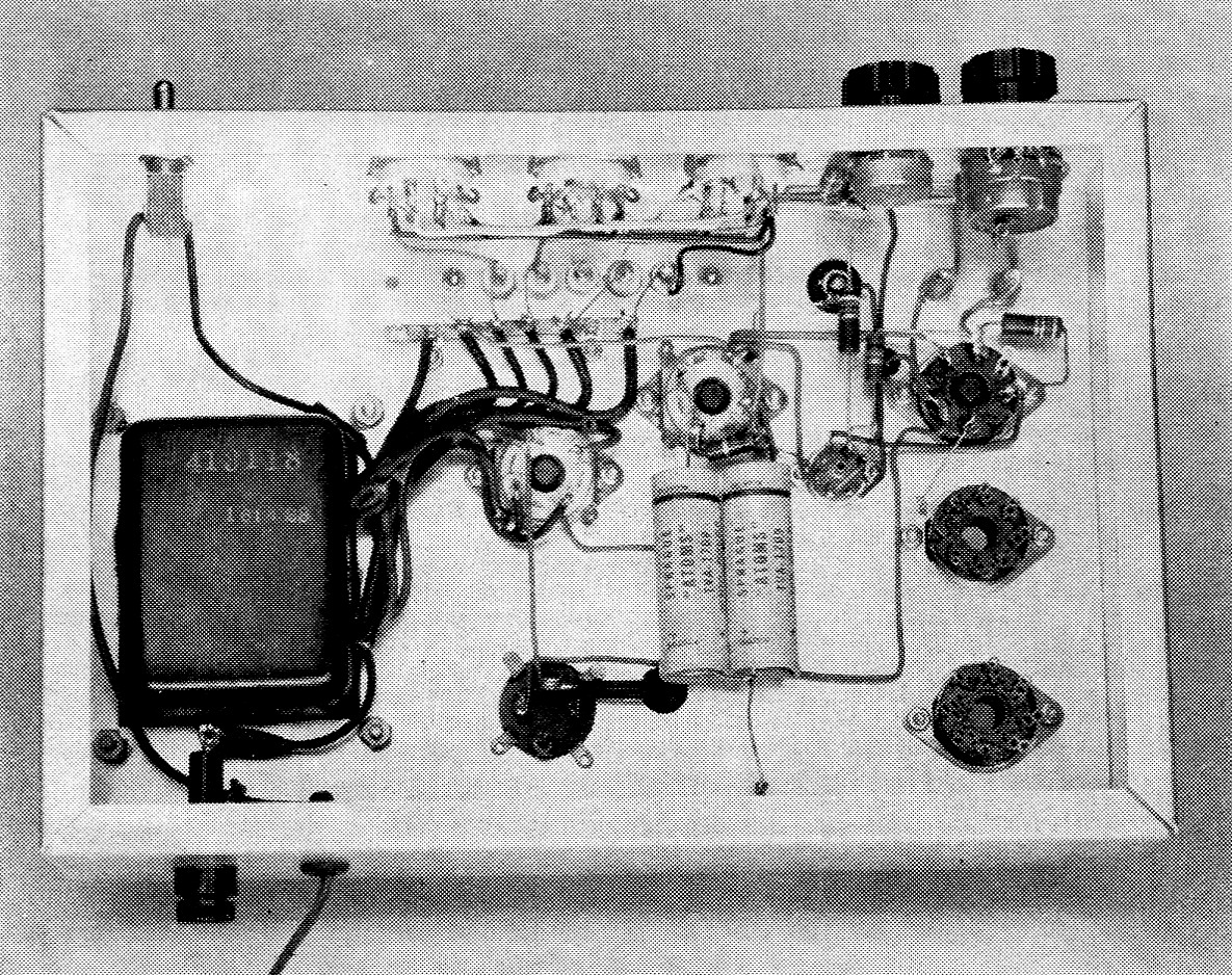
This bottom view shows the arrangement of the components below deck. At the upper right-hand corner is R7, the negative voltage control. This particular unit also has a single pole switch mounted on the control and we had planned to use it in place of S1. However, the switch was faulty (probably one of the reasons the TV set was junked!). The two electrolytic capacitors near the lower center are C3 and C4. Just to their left is the base of the canned electrolytic, C1 and C2.
Construction information
The complete supply is mounted on a 3 × 8 × 12 inch aluminum chassis. Component arrangement is not at all critical, but it is a good idea to mount the S1, R4, and R7 on the front of the chassis for easy access. The TV set we used had a fuse and holder, so this was mounted on the rear of the chassis where the a.c. line comes in. You don't have to fuse the supply but it is certainly worth the trouble and expense to protect the transformer and tubes.
Be sure to observe the correct polarity when mounting the electrolytic capacitors. In the power supply shown, C1-C2 is a dual unit, metal cased, taken from the TV set. You'll find data on the side of the can of capacitors of this type showing capacitance and voltage rating. In nearly all instances the metal case is negative and the terminals are positive. In the event that the capacitors you scrounge from your TV set do not have the same values as those given in Fig. 1, don't worry about it. The values are not critical and whatever capacitors were used in the TV set will provide adequate filtering for your supply. If the electrolytic you use from the set is dual type use the lower value capacitance for the input side of the filter (C1).
If you want to use a gas VR tube for a fixed regulated voltage you'll need a current-limiting resistor in series with the tube. Fig. 3 shows the method of connecting the VR tube in the supply. Also shown is the way two tubes can be connected in series to provide two different regulated voltages.
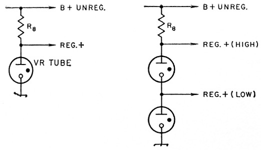
Fig. 3. Circuit showing method of connecting VR tubes to the utility power supply.
R8 is determined from the formula R = 1000 (Ea - Er)/I where R is the limiting resistance in ohm, Er is the voltage of the source across which the tube and resistor are connected, Er is the rated voltage drop across the VR tube, and I is the maximum rated current of the VR tube in milliamperes (usually 40 mA) For two VR tubes in series Er is the sum of the voltage drops across the two tubes. In the case of two tubes in series the upper tube must carry more current than the lower if a load is connected to the low tap. The total current drawn from both high and low taps should not exceed 30 to 35 mA.
Keep in mind that any voltage can be dangerous, and all terminals should be protected so that any danger of accidental contact with an exposed terminal is minimized.
Make a permanent record of the output terminal connections and keep it with the supply. Nothing can be so exasperating as to have to check through the circuit to find out which terminal has what voltage every time you use the supply.
Notes
- Haywood, "The spare-parts plutocrat," QST, July, 1961.
Lewis G. McCoy, W1ICP.