The big whell on two
Improved omnidirection coverage on 144 Mc with horizontal polarization.
For the two-meter buff, here is a new omnidirectional cloverleaf antenna with horizontal polarization. Large size results in improved bandwidth and coverage over the popular halo, and gives superior anti-flutter properties in mobile operation. Singly or stacked, the Big Wheel is also a boon for local work from the home station.
Anyone who has been involved in local two-meter net operation knows that there are many times when the directivity of a beam antenna is a handicap, and some of its gain could be profitably sacrificed for good omnidirectional coverage. For the mobileer, an omnidirectional radiation pattern is a must. For him, there is only the choice of sticking with the vertical whip or, if he wishes to avoid cross polarization with the rest of the fraternity, graduating to the halo or turnstile. In any event, there is a good case for the hori zontally polarized omnidirectional antenna on two meters. The question is only what type best serves the purpose.
Halos and turnstiles are surely steps in the right direction. The halo, particularly, has one marked disadvantage. It satisfies the polarization requirement and has a fairly good pattern, but it suffers from small "capture area." This means less bandwidth and gain, and worse mobile flutter characteristics than are possible with antennas of larger size. The turnstile is somewhat better, but it is still a small antenna.
To study possible advantages of large size, we started experimenting with the old threehalf-waves-in-phase type. This is a simple arrangement of three horizontal dipoles in a circle, fed in phase at the center, as shown in Fig. 1A. Illustrations of this antenna are found in the literture but design details are lacking. This turns out to be a problem since, due to mutual coupling, both impedance and resonant frequency depend on the geometry. Thus the usual dipole formulas do not apply. Results of early tests of crude models of this antenna showed great promise, particularly for mobile use, despite poor matching.
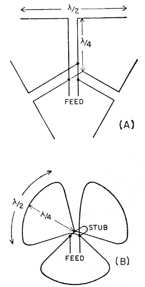
Fig. 1. Development of the "Big Wheel' started with three half waves in phase, as shown at A. Despite poor matching initially, this configuration showed promise and evolved into the cloverleaf style at B. Each element of the cloverleaf is one wavelength long. Feed impedance is brought to 50 ohms through the use of a tuning stub.
The design shown here evolved not so much from trying to improve the matching properties, but simply to try something new. Instead of using the center-connected transmission line, we decided to support the elements by feeders at each end instead of at the center, as shown at B in Fig. 1. This proved to be a fortunate choice, as it resulted in simpler construction, better mechanical stability, and more easily adjustable electrical properties. Now, each element is a full-wave loop, and it can be bent to try out various shapes and diameters. The idea is the same as before, however. The half-wave portions of the loop at the rim serve as radiators, while the radial portions at each end serve as quarter-wave feeders. Don't try to figure out where one ends and the other begins!
In designing this antenna, the first step was to settle on the shape of the elements. Various configurations were tried ranging from the most compact arrangement, a wheel consisting of three pie-shaped elements with an over-all diameter of about three feet, to a huge cloverleaf with oval-shaped elements and an over-all diameter of almost five feet. As a result of these experiments, we found that compactness makes matching and current equalization troublesome. Curiously, the radiation pattern is only slightly affected by the shape. For each of the elements there always remains a slight "front-to-back" ratio, roughly 3 dB. Variations in the pattern of this amount are barely noticeable in ordinary use. This observed pattern is shown in Fig. 2.
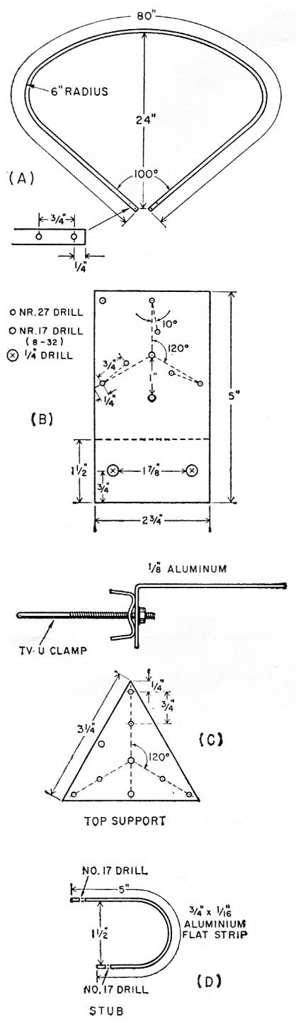
Fig. 3. Structural details of the Big Wheel 2-meter array. One element is shown at A. A wood dowel 2 inches long is driven into each element end to add strength.
The grounded lower support is shown at B. It is bent down at a right angle to permit mounting to a vertical pipe with a TV-type U clamp. The triangular top support is shown at C, and the tuning stub at D. The array is fed with 50 ohm coax, the inner conductor of which is connected to the upper support. Brass screws (¾ inch 6-32) are used to assemble the parts.
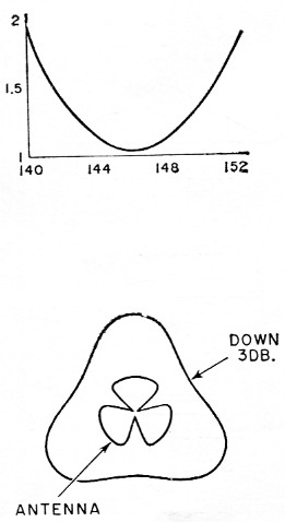
Fig. 2. Performance of the cloverleaf array. Frequency response can be controlled over a wide range, depending on the shape of the elements and over-all size. The configuration described is usable over the entire band if centered near 146 Mc.
There is a slight dip in the radiation pattern in back of each notch in the cloverleaf, but this is hardly noticeable in ordinary operation. In mobile work it is insignificant.
The next step was to trim the elements to length and adjust the stub for best s.w.r. at the desired frequency. Since all elements are fed in parallel at the low-impedance point, the input impedance would normally be quite low. Each has a radiation resistance of about 30 ohm in this configuration, which would give only 10 ohms for the parallel combination. To match to a 50 ohm line, the conventional stub-tuner scheme was used. Element lengths are chosen so that the impedance is capacitive and the circuit is then tuned to resonance with an inductive stub to give an input impedance of 50 ohm at the center frequency.
The design described here has an over-all diameter of four feet. It is no more critical or difficult to build than a three-element beam. Elements are made of 3/8 inch o.d. corrosion-resistant aluminum tube (Alcoa Type 6061-T6). The lengths are bent cold to the shape shown in Fig. 3. For good performance over the band, 80-inch lengths are used. The bracket and remaining hardware are prepared according to Fig. 3, and the elements mounted. Wood dowels are used to plug the element ends to provide strength and seal against moisture. The tuning stub is then cut to 5-inch over-all length, bent to shape and mounted as shown. Finally, the transmission line is prepared and connected. Keep the leads short or the s.w.r. will suffer. After assembly the structure is checked for conformity to dimensions and is ready to go.
As shown in Fig. 2, the s.w.r. should be 1.2 or better over the band. The pattern should be uniform to within ±2 dB.
Stacking the big wheel
Two of these antennas can be stacked for the home station with an increased array gain of about 4 dB. To improve the radiation pattern, the stacked antennas can be staggered by 60 degrees.
Stacking increases the directivity only in the vertical plane, while horizontal polarization and the omnidirectional pattern of the single antenna are preserved. This type of array is widely used in f.m., TV and beacon applications, where such properties are required. With the broad bandwidth and uncritical behavior of the Big Wheel, it is not difficult to realize considerable stacking gain by adding more bays before reaching the point of diminishing returns. In fact, results can be achieved in all directions which compare favorably with a small beam in its best direction.
Gain of a stacked array depends on both the number of bays and the spacing between them. In these experiments the optimum spacing of wavelength was used. Two-bay arrays were tested, showing a gain over a dipole roughly equivalent to a 2 element Yagi, but in all directions. It appears that 4, 6 or even 8 bays might be used,(1) but the point of diminishing returns is rapidly reached, as the number of bays must be doubled for substantial gain and the length of mast required becomes a problem.
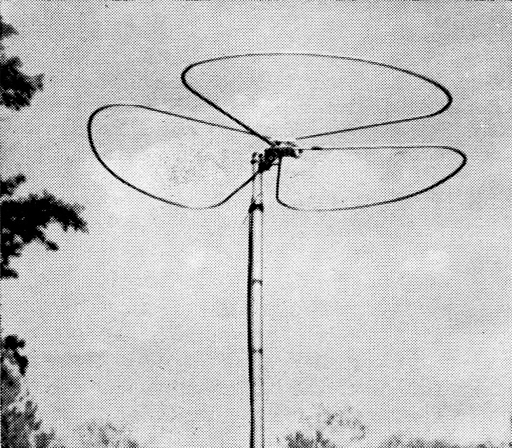
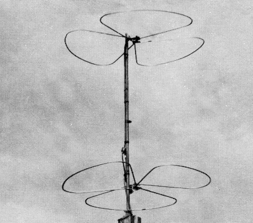
The 2-meter Big Wheel for mobile or fixed-station use.
With a bay spacing of 5/8 wavelength it is convenient to use full-wavelength phasing lines of coax. At 146 Mc 5/8 wavelength is approximately 50 inch, while for coaxial line a full wavelength is about 53 inch, due to the propagation factor of the line. The length of the coax is important, as both matching and phasing depend on it. The spacing is nominal, however, and it can be adjusted to make the phasing sections fit properly.
The arrangement for a two-bay antenna is shown in Fig. 4. A full wavelength of RG-11/U 75-ohm coax is used for the phasing section. It is driven by 50 ohm RG-8/U transmission line at a point ¼ wavelength up from the bottom, to achieve proper impedance transformation. The two ends of the coax are out of phase, so one of the bays must be turned upside down to put the antenna currents in phase.
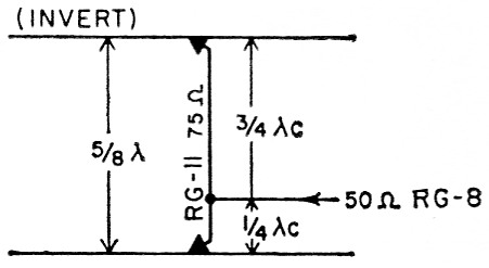
Fig. 4. Stacking method for two Big Wheel antennas. Because of the propagation factor of coaxial line, an electrical full wavelength of coax, Xc, is approximately s/s wavelength long. This is the optimum stacking dimension for dipoles. By using a 75 ohm phasing line the system may be fed at the point indicated with a 50-ohm transmission line. Note that one bay must be inverted to keep antenna currents in phase.
When the original 5 inch stubs were used, it was found that the point of minimum s.w.r. had shifted from 146 to 148 Mc, due to coupling between the bays. This was corrected by increasing the stub length from 5 to 6 inch total length. The resulting s.w.r. curve is almost identical to that of a single antenna. With the bays staggered 60 degrees on the mast the pattern variations are negligible. Gain is approximately 4 dB over a dipole.
For both mobile and fixed station, the Big Wheel has performed beyond our fondest hopes. Mobile results are particularly astonishing, as the troublesome rapid flutter is remarkably reduced. Our best testimonial was the occasion when one operator said he couldn't believe that such a strong, steady signal was coming from a moving car at such a great distance. At home it's a pleasure to be able to hear everyone in the Shoreline Net without continually fussing with a rotator.Notes
- Extensive tests of the Big Wheel have been made by the editor, both at the home station and in the field. The single-bay clover-leaf array has given performance superior to any other single omnidirectional antenna yet tried, and the two-bay system is all that the authors claim. In portable work, particularly, it has been found that a two-bay Big Wheel brings in signals with a strength comparable to that achieved with small Yagis, yet it delivers this performance in all directions and over a wider frequency range than is obtainable with parasitic arrays. Tests are currently underway with a four-bay system and results will be reported at a later date. - W1HDQ
Robert H. Mellen, W1IJD
Carl T. Milner, W1FVY.